3PAR StoreServ 7000 Hardware – Part 2

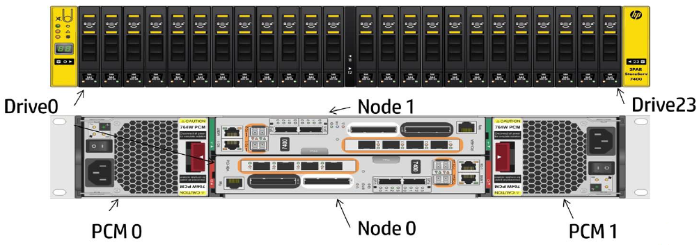
In the first blog post we covered an overview of the StoreServ 7000 hardware the next stage is looking at ‘what we do next’.

Setup A StoreServ VSP

The Virtual Service Processor comes as an Virtual Appliance in the OVF format, this can only be installed on ESXi 4.1, 5 or 5.1.  From a design perspective it’s not a good idea to have the VSP on the StoreServ.  Why’s this you ask?

Well, the VSP is responsible for reporting back any issues to 3PAR Central that the StoreServ has.  If the VSP is on the Virtual Volumes provided by the StoreServ then how can it report back ? The answer is it can’t.  Recommended practice is to place the VSP on a RAID protected local HDD of an ESXi host.

I’m not able to walk through deploying the OVF VSP as it doesn’t appear to have been released for download and therefore it’s likely to only come with a DVD media kit when ordering the product.  From the installation guide, the only thing to note is that it’s recommended to use Thin Provisioning.

After launching the OVF you need to login to the VSP, my understanding this will be via SSH like the F400’s.

U: root

P: hp3par

Once logged in, the VSP would have obtained an IP Address from DHCP, run the command

ifconfig -a

Which will return the IP Address to enable the HP SmartStart software to connect to allow configuration of the VSP.

SmartStart

SmartStart requires Windows Server 2008.  It is the software used to configure your StoreServ 7000.

A couple of items to note:

  1. You require Administrator access on the Windows Server 2008.
  2. VSP and the StoreServ 7000 much be on the same subnet as the Windows Server 2008 running are running SmartStart on.

The screen shots below are taking from the HP training, hopefully the process makes sense without me actually having an actual StoreServ to configure!

Initial SmartStart Welcome Screen

SmartStart Welcome Screen

Prepare to Configure

SmartStart Prepare To Configure

This is the part where you now want to ‘click’ on Setup Service Processor and enter the IP Address you received from running the ifconfig -a command and login using root hp3par

SmartStart Setup Systems

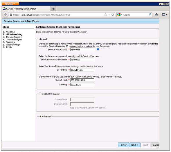
The SP Setup Wizard will then launch on a Web Page.

SP Setup

Next you will enter some basic networking details which are:

  • Service Processor ID, I believe this is obtained from HP
  • Service Processor Hostname e.g. StoreServ-VSP001
  • IP Address
  • Subnet Mask
  • Default Gateway
  • Domain Name
  • DNS Server(s)

SP Networking

Next you need to configure the support package.  You have three choices:

  • Active – this allows HP to remotely perform maintenance tasks on the Virtual Service Processor and StoreServ.  Log files are automatically sent to HP.
  • Passive – this sends log files only
  • No Support – you need to send log files manually

SP Remote Suppport

Next enter your Time Zone and enter a NTP server.  My recommendation is to use an internal DC as your NTP server to avoid time skew.

SP NTP

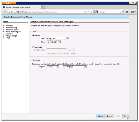
Lastly, you confirm your settings and apply them.  Naturally, your IP address will change so remember that you will need to reconnect to this to make any further changes.

Setup StoreServ 7000

Back to the SmartStart and the next thing we want to do is select ‘Set up the Storage System’.

Setup StoreServ

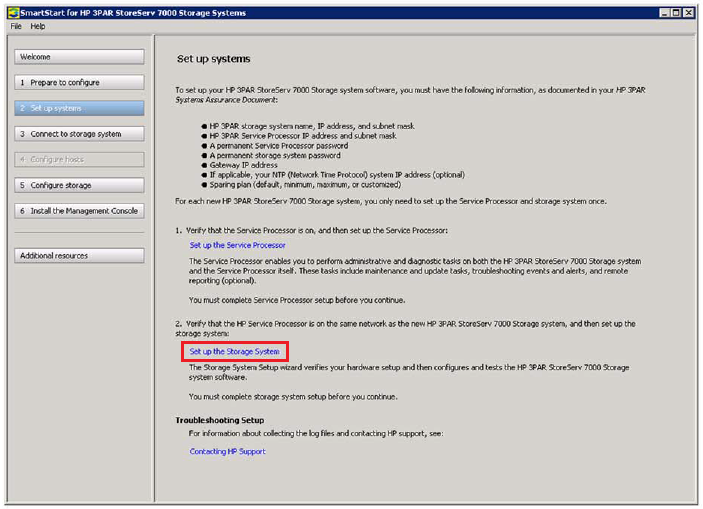
This takes you back to the Virtual Service Processor, so you need to login with U: root P: hp3par

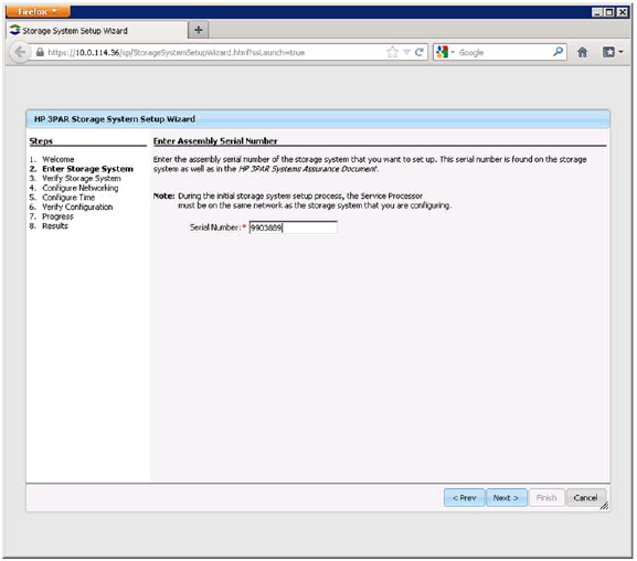
Click next a couple of times and then at this point you will need to enter the ‘assembly serial number’ which is on the StoreServ or your HP 3PAR System Assurance Document.  To be clear this is the serial number for the complete StoreServ not an individual component.

StoreServe Serial Number

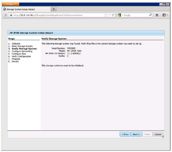
The StoreServ is then verified with the model, 3PAR OS version and the number of Nodes, hits next.

Verify StoreServ

Enter networking information for:

  • Hostname e.g. StoreServ-001
  • IP Address
  • Subnet Mask
  • Default Gateway

StoreServ Networking

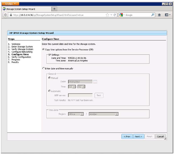
Next we configure the time, it is recommended to get the time from the Virtual Service Processor

StoreServ NTP

Lastly, click Next and verify the installation.

3PAR StoreServ 7000 Hardware – Part 1

This is the first in a series of blog posts as I work towards the HP ASE – Storage Solutions Architect

One of the issues I have had when learning the new range of HP products is the naming convention, so below is my ‘dummies guide’.   If I have gotten any of these wrong, please let me know.

Old 3PAR New StoreServ

Old LeftHand New StoreVirtual

Old ‘X’ NAS Range New StoreEasy

Old P2000 New StoreSure

Old Storage Networking New StoreFabric

Old Tape Drives New StoreEver

Old IBRIX New StoreAll

Old DataProtector New StoreOnce

StoreServ 7000

Essentially this is a replacement for the F200 and F400, it is meant to be customer installable, but as you can see from the issues that Justin Vashisht had when installing a StoreServ 7200, I think this is a work in progress whilst HP get to grips with the ‘SmartStart’.

The StoreServ 7000 comes with a Virtual Appliance (OVF) aptly named the ‘Virtual Service Processor’ which runs on ESXi5 or above.  It is recommended not to install the Service Processor on the StoreServ rather on either local drives.  Note you can obtain a Physical Service Processor if required.  The Service Processor used to come as a 1U server and is used to send remote error detection and reporting to ‘HP 3PAR Central’

The StoreServ 7000 can use SAS and SATA drives in both SFF and LFF.  For both hard drive type SSD are available.  Note that no Fiber Channel drives are available.

3PAR Controller

StoreServ likes to use ‘0’ alot, so you need to remember that Nodes start with 0 same with Drive Bays!

The StoreServ 7000 comes in two flavors:

7200 – Two Node Chassis

The base enclosure comes with:

  • 2 Nodes
  • 4 FC Ports
  • 24 SFF Slots
  • 24GB Cache (8GB Control Cache & 4GB Data Cache Per Node)
  • 1.8 GHz Quad Core CPU
  • 2 x 1 Gb ports for Management & Remote Copy

For extra storage capacity upto five additional disk cages can be added either SFF or LFF giving a total of 144 drives.

7400 – Two Node Chassis

The base enclosure comes with:

  • 2 Nodes
  • 4 FC Ports
  • 24 SFF Slots
  • 32GB Cache (8GB Control Cache & 8GB Data Cache Per Node)
  • 1.8 GHz Hexa Core CPU
  • 2 x 1 Gb ports for Management & Remote Copy

For extra storage capacity upto nine additional disk cages can be added either SFF or LFF giving a total of 240 drives.

Can be upgraded to four node configuration.

For HBA’s you can add an optional:

  • 4 Port 8 Gb/s FC which can be used for SAN connectivity or Remote Copy.
  • 2 Port 10 Gb/s iSCSI/FCoE, note that FCoE isn’t yet supported.

3PAR Comparison

Sometimes a picture speaks a thousand words, the picture below shows the connectivity at the back of each StoreServ node

3PAR Connectivity

7400 4 Node Interconnect

When deploying a 7400 4 Node we need to follow the correct cabling schema.  HP have been quite smart and introduced a ‘black to white’ and ‘white to black’ chema, however it’s not clearly labelled, so for the avoidance of doubt.

Controller A, Node 0, Interconnect 0 >> Controller B, Node 2, Interconnect 1

Controller A, Node 0, Interconnect 1 >> Controller B, Node 3, Interconnect 0

Controller A, Node 1, Interconnect 0 >> Controller B, Node 3, Interconnect 1

Controller A, Node 1, Interconnect 1 >> Controller B, Node 2, Interconnect 0

3PAR Interconnect

Disk Shelves

Disk Shelves comes in two flavors:

H6710 which is a  2U 24 Bay SFF Drive Chassis.

Drives should be installed left to right with a minimum of two drive increments.

3PAR H6710

H6720 which is a 4U 24 Bay LFF Drive Chassis

Drives should be installed bottom to top with a minimum of two drive increments.  Note that all columns should contain the same drive type e.g. 600GB 15K SAS

3PAR H6720

On both disk shelves, DP-1 is IN and connects to the original Nodes.  DP-2 is OUT and connects to additional disk shelves.

One of the slightly tricky parts is the disk shelf cabling.  Some rules to follow:

  • Event Nodes go to Even Controllers
  • Odd Nodes go to Odd Controllers
  • Odd Nodes connect to the highest Disk Shelf first
  • Even Nodes connect to the lowest Disk Shelf first

3PAR Disk Shelf Cabling

Relay vCenter Alert Emails Externally

I was fortunate enough to have a second post published on the VMware SMB Blog site.  This particular post is an issue that I faced quite a while back, but it still holds true if you are trying to relay vCenter alerts externally.

From the Bloggers Bench: Relay vCenter Alert Emails Externally

When configuring your vCenter environment, most if not all VMware Administrators will set up email alerting. I covered the configuration of this in Setting Up & configuring Alarms In vCenter Part 1.

Unfortunately, if you leave Exchange 2010 using its Default Receive Connector, you will only receive alerts internally e.g. to the domains which Exchange 2010 is authoritative. This causes a problem if you need to send alerts to a third party e.g. Managed Service Provider.

To demonstrate the issue, I have connected to a vCenter server and then I’m going to telnet to an Exchange 2010 CAS Server on port 25 by issuing the command:

telnet VMF-EX01 25

Once in enter the following:

EHLO
MAIL FROM: vmware@testdomain.co.uk
<Press Enter>
RCPT TO: craig@vmfocus.com
<Press Enter>

Read more over at the VMware SMB Blog