VMware View – Objective 2.10 Configure The Environment For Local Mode

Knowledge

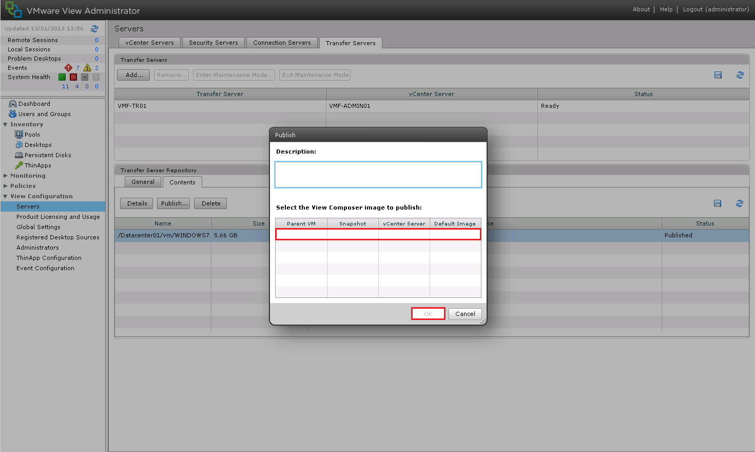
  • Publish linked clone replica to Transfer Server repository
  • Identify Local Mode policies
  • Configure Local Mode policies
  • Ensure client device meets Local Mode requirements (e.g., proper version of View Client, hardware requirements, disk space, end device resource requirements, etc.)
  • Verify transfer server configuration

Local Mode is one of the features of View that I’m most excited about exploring.  In the past I have used XenApp Offline Applications and that was a world of hurt!  I mean how cool is it to be able to take your VDI offline and use it whilst flying or on a train.  Naturally, we do have a few prerequisites, which we will cover off during this port.

View Offline Desktop

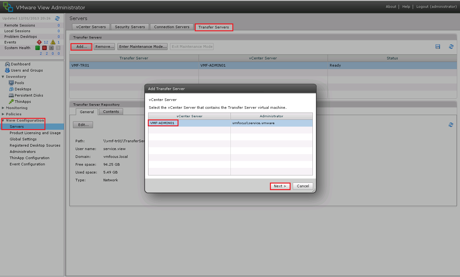
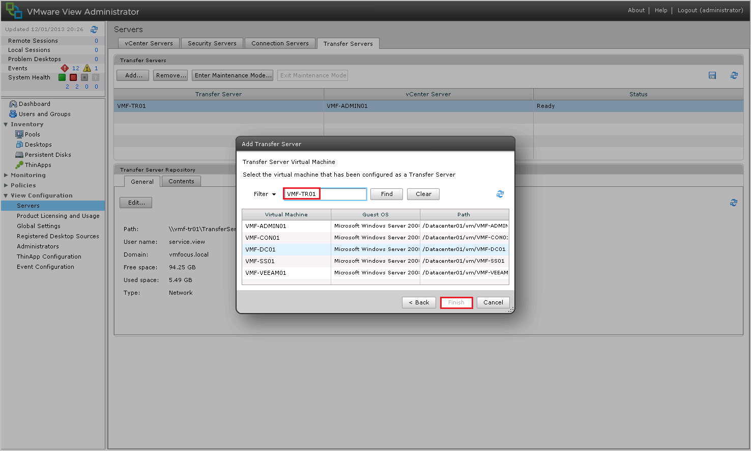
Publish Linked Clone Replica To Transfer Server Repository

The good news is we have already covered this over on Objective 2.5 – Configure View Transfer Servers  so we can move straight onto the next item.

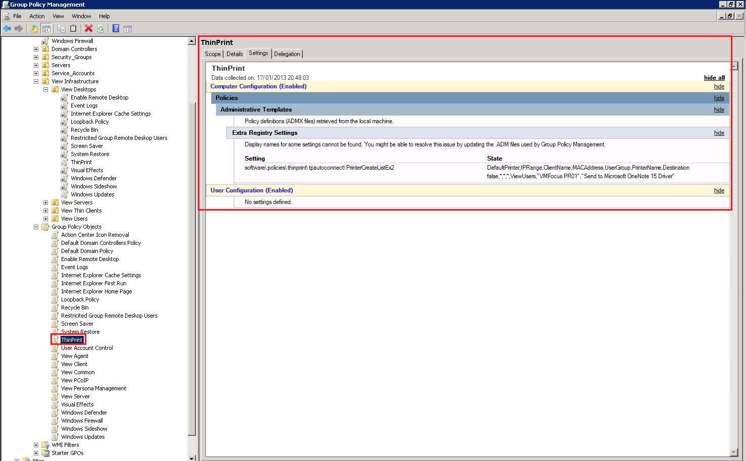
Identify Local Mode Policies

By default Local Mode is disabled, it has to be enabled in Global Policies.  These can be found in the View Administrator under Policies.

View Local Mode 1

A quick breakdown of the Local Mode Policies are:

Local Mode: Needs to be enabled to allow Local Mode Desktops

User Initiated Rollback: When a user wants to check there desktop back in, with this feature enabled they can either check the desktop in and all the changes are synced back to View or they can choose to roll there desktop back to the version on View discarding any changes they have made when working offline.

Max Time Without Server Contact: This is the amount of time the user can be offline for.

Target Replication: We can’t always rely on users to ‘check in’ desktops so this feature will try and replciate any changes at a given interval.

User Deferred Replication: Can the user choose not to replicate?

Disk Replicated: By default only the persistent disk is replicated as this contains all of the users information such as desktop icons and my documents.  You can choose to replicate the OS disk as well.

User Initiated Check In: Is the user allowed to check there desktop in?

User Initiated Replication: Is the user allowed to start replicating changes back to View?

View Local Mode 2

Ensure Client Device Meets Local Mode Requirements

We have a few requirements to meet with Local Mode, so let’s rattle through them.

Operating System Requirements

  • Only supported on Windows systems
  • Windows 7 32 or 64 Bit Home, Professional, Enterprise or Ultimate
  • Windows Vista 32 Bit Home, Professional, Enterprise or Ultimate SP1 & Sp2
  • Windows XP Home and Professional SP3

As you can see the physical desktop doesn’t have to be part of the Active Directory domain as ‘home’ version works.

Physical Hardware Requirements

  • CPU needs to be 1.3GHz or faster
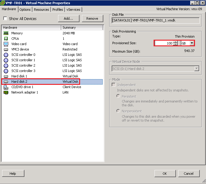
  • Disk space required is as much as what the VM can grow to e.g. View Desktop uses 10GB but has 20GB allocated, you need to have 20GB free.
  • 2GB Memory Windows XP and Vista
  • 3GB Memory Windows 7
  • BIOS must support Hardware Virtualisation

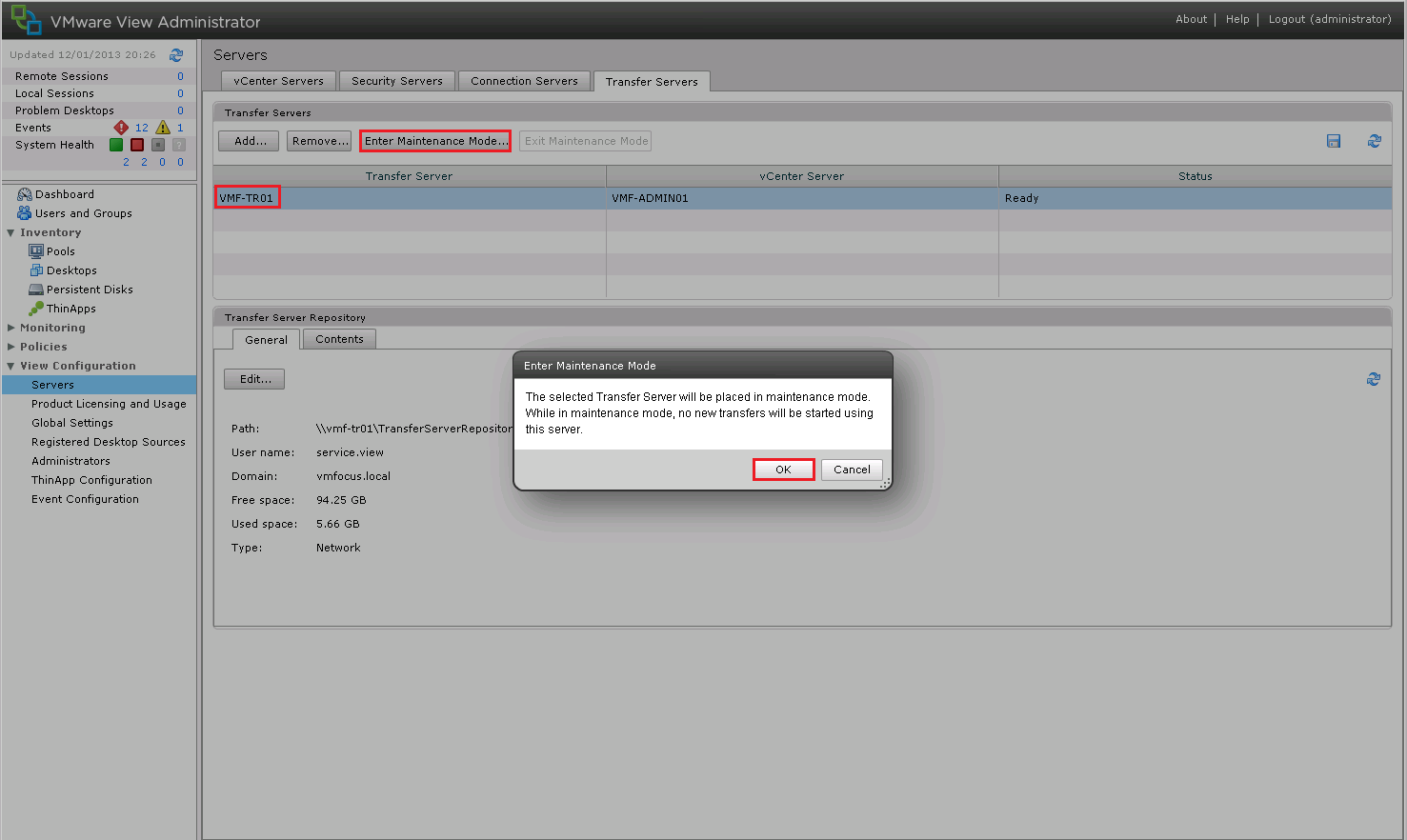
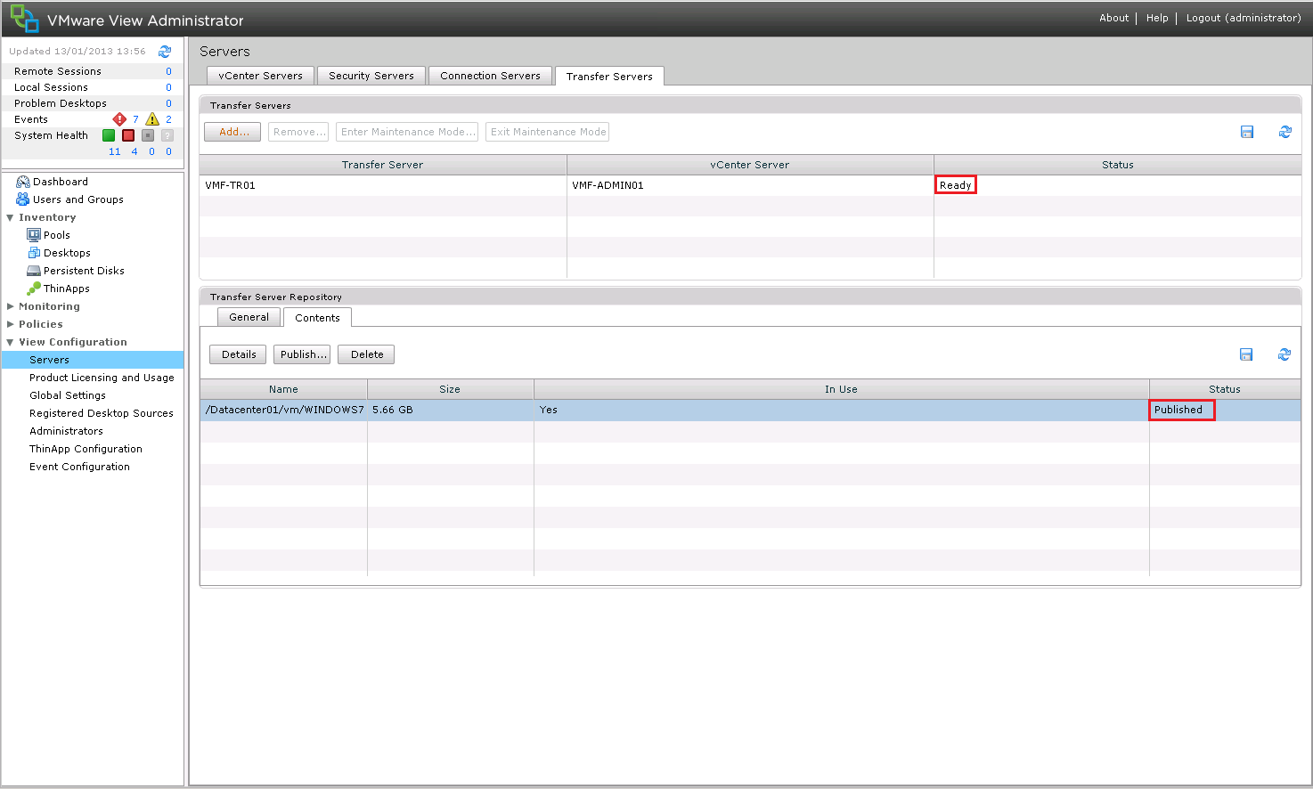
Verify Transfer Server Configuration

The only real way to do this is to give the bad boy a whirl!

First thing to do is check your transfer Server is ready to rock and roll under View Configuration > Servers > Transfer Servers make sure that:

  1. Status Ready
  2. Snapshot is Published

View Local Mode 3

At the moment my View Client doesn’t have Local Mode installed, so I’m going to run the View Client Installer with Local Mode, at the time of this blog post, the most upto date version is VMware-viewclientwithlocalmode-x86_64-5.2.1-937772

Hit Next and we want to Modify the installation

View Local Mode 4

Select View Client with Local Mode and hit Next

View Local Mode 5

Click on Install

View Local Mode 6

Click Finish

View Local Mode 7

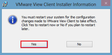
Unfortunately, Local Mode requires a reboot, so I will see you on the other side!

View Local Mode 8

Before we move forward, a couple of things about Local Mode.

  1. The desktop can only be checked out if it’s powered off.
  2. The desktop can only be checked in if it’s powered off.

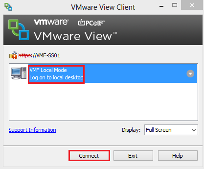
I have logged in with a user who has rights to use Local Mode on a View Pool.  The desktop is shut down, we want to click the Down Arrow and Select Check Out

View Local Mode 9

Did you spot the VMware Octopus as my desktop background?

We are going to select OK (however you can change the download location of the desktop from the default if you wish).

View Local Mode 10

You will see the percentage start to increase.

View Local Mode 11

What happens is that View takes a snapshot of your Desktop VM and places a Lock on it so no changes can be made (makes sense as it can’t be used).

View Local Mode 12

Time to grab a cup of tea, as this takes a while.

Excellent the check out has completed, click Connect.

View Local Mode 13

When you login, Windows will need to restart to identify the new hardware it is running on.

View Local Mode 14

That’s it for this objective, I think you will agree with me, Local Mode is proper awesome and takes down many of the barriers that CTO may have had with VDI in the past.

VMware View – Objective 2.9 Configure Remote and/or Location Based Printing For View Desktops

Knowledge

  • Describe ThinPrint architecture
  • Identify ThinPrint services
  • Register .dll file
  • Configure GPO
  • Import location printing ADM file

Printing is the nemesis of the VDI world, how do we get that PDF from the View Desktop to the users client and enable everyone else to work?  We are now entering into the promised land.

OK, I have a confession to make, I despise printers, they are the root of all evil and probably the biggest pain for Desktop Support Engineer.  I don’t actually own a printer and to be honest, nor do I want to, so this particular objective is going to be theory based (well at least for me).

Now that I have that off my chest, I think we can carry on with Objective 2.9 Configure Remote and/or Location Based Printing For View Desktops

Describe ThinPrint Architecture

Before we talk this printing malarkey, it’s probably an idea to get an understanding of the steps taking to print inside a VDI environment.

In a traditional physical Desktop environment, the print flow is:

Physical Desktop User Prints > Desktop Print Spooler > Print Traffic Sent Across Network/USB > Print

The VDI environment follow the same principle, however the printer isn’t directly connected by LAN or USB.

View Desktop User Prints > Print Traffic Sent To Physical Windows Desktop > Physical Desktop Spooler > Print Traffic Sent Across Network/USB > Print

Now this isn’t so bad when working on the LAN, as the configuration we aren’t so worried about bandwidth, but when we are printing over a WAN, then we have some dramas!

VMware understood the challenges faced with printing inside the VDI environment and they licensed Thin Print under an OEM Agreement.

When you install the View Agent and the View Client, the ThinPrint drivers are automatically installed.

The print process works in the same way that I described above, however the print job is compressed and encrypted.  The steps are:

  1. User prints inside View Desktop, the print job is captured by the ‘ThinPrint Generic Driver’ which is automatically installed as part of the View Agent into the View Desktop.
  2. The print job is compressed by the ‘ThinPrint Generic Driver’ and then sent over the WAN to the Windows Physical Desktop.
  3. The Physical Windows Desktop (which has View Client installed) then decompresses the print job and sends it too the print spooler.
  4. The Physical Windows Desktop then spools the print job to the printer.

Print Drivers

I wanted to take a slight detour and talk about Printer Drivers.  The Print Driver needs to be available for the print job to happen, this can be achieved in a few ways.

Physical Windows Desktop this option can work if you are reusing old Windows Desktops to be your ‘dumb terminals’ . Just install the Print Drivers on the physical desktop.

Thin Client this causes us an issue as we cannot install any Print Drivers, as we have no host Operating System.  In this case we need to install the Print Drivers into the View Desktop.  If you have a Desktop Pool that is used company wide which has 50 printers, you don’t really want to ‘bloat’ your Linked Clone Image with all the drivers.  Instead you probably want to install Print Drivers on demand, which is something I will refer to later in this blog post.

Identify ThinPrint Services

We have two services which are installed on the View Desktop which are:

  • TP AutoConnect Service
  • TP VC Gateway Service

View Thin Print Services

The TP AutoConnect Service creates the printers in the users View Desktop

The TP VC Gateway Service is the grafter, it grabs the print data from the applications to enable it to be encrypted and compressed.

On the View Client (Physical Windows ) Desktop we don’t have any services installed, as it’s within the View Client, however we do have a registry key that we can alter to enable or disable ThinPrint.

Enabled HKEY_LOCAL_MACHINESOFTWAREWow6432NodeThinPrintClient Default State 0

Disabled HKEY_LOCAL_MACHINESOFTWAREWow6432NodeThinPrintClient Default State 1

View Client ThinPrint Registry

Register .dll File

To allow us to access the Group Policy settings for ThinPrint we need to register a .dll on an Active Directory Domain Controller.

The .dll is called TPVMGPoACmap.dll and is located on your Connection Server under C:Program FilesVMwareVMware ViewServerextrasGroupPolicyFilesThinPrintx64

Register DLL 1

Copy this .dll to the root of your Domain Controller.

Jump into the CMD and type regsvr 32 C:TPVMGPoACmap.dll

Register DLL 2

Boom, we have success!

Register DLL 3

Configure GPO

This is really straight forward, first of all we need to create a Group Policy, I’m rolling with a GPO called ‘Location Based Printing’ and I have linked it to the Organisational Unit ‘View Desktops’

Naturally, the GPO is blank at the moment.  Let’s edit it and go to Computer Configuration > Policies > Software Settings and you will see AutoConnect Map Additional Printers for VMware View

ThinPrint GPO 2

Double Click AutoConnect Map Additional Printers for VMware View and set the Policy to Enabled by Clicking in the Top Right Hand Corner

ThinPrint GPO 3

Import Location Printing ADM File

We have really imported the location ADM file by performing the above, I wanted to give you an overview of the Location Printing settings.

Click Add in the top left and you will see some columns appear ‘as if by printer magic’.

ThinPrint GPO 4

We can define who can access the printer by:

  • IP Range
  • Client Name
  • MAC Address
  • User/Group

In most environments it’s probably going to be via IP Range or User/Group

The Printer Name column, is the name we want the printer to appear as in the View Desktop.

The Printer Driver column, is really important, this is the driver which is installed on the Physical Desktop.  Ensure that you type this in exactly as it appears on the Physical Desktop.

If the printer is locally attached then you don’t need to enter any details in under the IP Port/ThinPrint Port.  If you are using a network printer then you need to enter it in the format IP_x.x.x.x e.g. IP_192.168.1.10

As you can see I have entered the details in for my Microsoft OneNote driver into AutoConnect Map Additional Printers

ThinPrint GPO 5

If we now check the ThinPrint Group Policy out you will see we have Extra Registry Settings Configured.

ThinPrint GPO 6

VMware View – Objective 2.8 Configure Role Based Administrators

Knowledge

  • Identify required folders
  • Create View folders for delegated administration and roles
  • Set permissions on a folder
  • Create the administrator roles
  • Assign folders and roles to user and/or groups

Identify Required Folders

View’s Permissions are based around Folders, and are designed to work with each Desktop Pool, so you can different View Administrators   for different users if you so wish.

The good news is I have covered all of the knowledge except for Creating View Folders already in VMware View – Objective 2.3 Configure View Standard & Replica Connection Servers under Section Identify Default Roles, Custom Roles, and What Permissions Are Available

To create a View Folder go to Inventory > Pools and Select Folder > New Folder

View Folder 1

Enter your Folder Name and Hit OK

View Folder 2

VMware View – Objective 2.6 Configure Advanced Display Protocol Settings (PCoIP/RDP)

Knowledge

  • Reference GPO templates
  • Describe RDP requirements
  • Locate ADM template files
  • Explain GPO settings including Describe “build to lossless” and Describe how to configure cache size
  • Identify maximum number of monitors and resolution
  • Configure Flash quality and throttling
  • Configure software 3D rendering capabilities

Reference GPO Templates

View comes with a number of built in Group Policy templates which are as follows:

View GPO

For a full break down of each Group Policy setting, I recommend reading the VMware View Administration – View 5.0 guide.

Describe RDP Requirements

To enable users to connect to there View Desktop, RDP has to be enabled on the Operating System.  When they grant the View Desktop Users access to a Restricted Group called ‘Remote Desktop Users’ and apply this group policy to the Organisational Unit that the View Desktops will be held.

I covered the configuration steps in VMware View – Objective 1.5 Preparing Active Directory For Installation under Section Remote Desktop Users.

The requirements for RDP are as follows:

  • Remote Desktop Connection 6.x > Windows XP
  • Remote Desktop Connection 6.x or 7.x > Windows Vista
  • Remote Desktop Connnection 7.x > Windows 7

The good news any of the above RDC protocols support dual monitors!

Locate ADM Template Files

The ADM Template Files are located on your View Connection Server under …VMwareVMware ViewServerextrasGroupPolicyFiles

A bit like Blue Peter, I made this earlier which shows you how to import the ADM Templates VMware View – Objective 1.5 Preparing Active Directory For Installation under Template Files.

Explain GPO Settings Including Describe “Build To Lossless” and Describe How To Configure Cache Size

I feel like a parrot repeating myself, but here goes, for a full break down of each Group Policy setting, I recommend reading the VMware View Administration – View 5.0 guide.

One of the most important features of the PCoIP protocol is ‘build to lossless’ so what does this actually mean.  Well the essence of ‘build to lossless’ is to give the user the best experience possible.

Let’s say a user is in a cafe, and the are using there mobile phone to act as there WAP.  The likelihood is the connection will have high latency and there bandwidth is probably less than 1 Mbps. Rather than sending the complete desktop image immediately, the PCoIP protocol will send it in a ‘lossy’ state first which is a highly compressed initial image.  As the connection continues more data is sent and the ‘lossy’ initial image becomes fully rendered.

The good news is the user, has no idea this is going on in the background, they just think it’s sheer awesomeness!

PCoIP is a clever little protocol, as it uses the clients (dumb terminal) memory to cache portions of the display to save them having to be re-transmitted and re-rendered.  Currently this setting is only supported in Windows and Linux.

The VMware View PCoIP Session Variable ADM contains the setting.  If this isn’t configured or enabled then PCoIP uses 250MB.  If you do configure it, then the minimum setting is 50MB and the maximum is 300MB.

To get to this settings open up Group Policy Editor > View PCoIP > Computer Configuration > Policies > Administrative Templates > Classic Administrative Templates > PCoIP Session Variables > Not Overridable Administrator Settings > Configure PCoIP Client Image Cache Size Policy

PCoIP Client Image Cache Size Policy

Identify Maximum Number Of Monitors and Resolution

If you really want too, you can have four monitors running up to 2560 x 1600 display on each!

Or if you want to roll with 3D enabled, then I’m afraid it’s only two monitors at 1920 x 1200.

Configure Flash Quality and Throttling

Before we go into the configuration, a couple of items about Flash.

  1. Bandwidth reduction is only available in Internet Explorer with Flash version 9 or 10.
  2. Flash cannot be running in full screen mode

Flash settings are configured per pool.  To change settings go too Inventory > Pools > Edit Pool Settings > Scroll Down to Adobe Flash Settings

Flash Settings

Naturally, you can select the Flash settings that work best for your environment.

Configure Software 3D Rendering Capabilities

So you really want to use the Windows 7 Aero theme? Well good news is that View supports it, however you need to make sure the following requirements are met:

  • ESXi 5.0 or later Hosts
  • vCenter 5.0 or later
  • Desktops must use Virtual Hardware 8 or later
  • PCoIP must be used
  • Users cannot choose there own display protocol

To enable 3D Rendering go too Inventory > Pools > Edit Pool Settings and change the following:

  • Default display protocol PCoIP
  • Allow users to choose protocol No
  • Windows 7 3D Rendering Enabled

3D Rendering

VMware View – Objective 2.5 – Configure View Transfer Servers

Knowledge

  • Identify Transfer Server repository
  • Identify vCenter Server that contains the Transfer Server
  • Identify the Transfer Server virtual machine

I’m not going to follow protocol on this blog post, as I want to show you the configuration steps, you will see by doing this we cover the objectives above with ease.

The Transfer Server Repository is the location for your Linked Clone Replicas (the snapshot of your original Operating System) or your Manual Desktop Pool.  It’s worthwhile noting that the Transfer Server can only be used with Dedicated Desktops, not Floating Desktops.

If you are rolling with Linked Clones, then you need to Publish your Snapshot which is the base image for your Linked Clone Pool.

Couple of caveats before we move forward:

  • Make sure your VM is running Hardware Version 7 (at the time of this post 8 is meant to be supported but I haven’t tested it yet).
  • Make sure that your Transfer Server SCSI Controller is set to LSI Logic Parallel

The Transfer Server Repository can be a network share located on another server or NAS, or in my case it’s an extra VMDK added to the VMF-TR01.

I have already added my Transfer Server into View to make sure I had it working before I did a blog post!

However, the process to enable the Transfer Server is fairly straight forward, go to View Configuration > Servers > Transfers and Select Add and choose your vCenter Server

View Transfer 1

Select your Transfer Server from the drop down list and Click Finish

View Transfer 2

Next we need to add some images to our Repository, so click on Transfer Server Repository and Click Edit and we get an epic failure ‘the settings for the Transfer Server repository cannot be edited until all the Transfer Servers are placed into maintenance mode’.

View Transfer 3

Simple fix, we just need to do what View tells us.  We need to Enter Maintenance Mode, by virtue of this, no new transfer will be able to take place, so bear this in mind in production.

View Transfer 4

Cool, now we are in Maintenance Mode, we can add an Image to our Repository.  First thing we are going to do is add another HDD to our Transfer Server.  You can see that I have added a 100GB VMDK Thinly Provisioned

View Transfer 5

In this instance, I have created a D: Partition called Data and a Folder named ‘TransferServerRepository’

View Transfer 6

This folder has then been shared out and I have given the Active Directory User ‘service.view’ Read, Write and Modify permissions.

Back to View Administrator and we want to Edit the Transfer Server Repository and enter the following details:

  • Network Share \vmf-tr01TransferServerRepository
  • User Name service.view
  • Password Password
  • Domain vmfocus.local

View Transfer 7

Now we need to Publish our Snapshot to the Transfer Server Repository.  Hit the Contents Tab and Click Publish and we get another epic fail ‘Publishing is not enabled because no Transfer Servers are currently working properly’.

View Transfer 8

The reason being we are still in ‘Maintenance Mode’ so lets ‘Exit Maintenance Mode’ and try again.

Cool, select your View Composer Image and Click OK (mines already been uploaded).

View Transfer 9

This is going to take quite a while, so it might be worth grabbing a cup of tea.

Once it’s all done you should see that the Image is Published and the Transfer Server is Ready.

View Transfer 10

That’s this objective done, we play around with the Transfer Server in a bit more detail during Objective 2.10