How To See Local RAID in ESXi 5.1

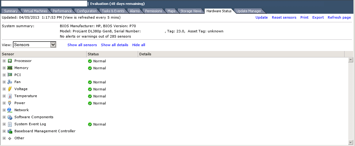
One of my work colleagues Mat Smith pointed out that when you install the generic ESXi hypervisor from the VMware site you get basic HP or Dell hardware information which is OK, but if you only have local storage you don’t know what state the underlying RAID configuration is in unless you have access to iLO or DRAC.

ESXi01 Hardware

This can be easily rectified by downloading the latest HP Custom Image for ESXi 5.1.0 ISO at the time of writing this blog post, the latest update is VMware-ESXi-5.1.0-799733-HP-5.34.23.iso

Once you have downloaded the ISO go into Update Manager > Admin View > ESXi Images and Select Import ESXi Image

ESXi Images 1

Select your the HP Custom Image for ESXi 5.1.0 ISO and click Next

ESXi Images 2

It should only take a minute or so and you will see the HP Custom Image for ESXi 5.1.0 ISO has been uploaded.  Once done hit next.

ESXi Images 3

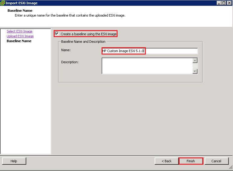
Next we need to create a a baseline image, I’m going to roll with HP Custom Image ESXi 5.1.0 then click Finish

ESXi Images 4

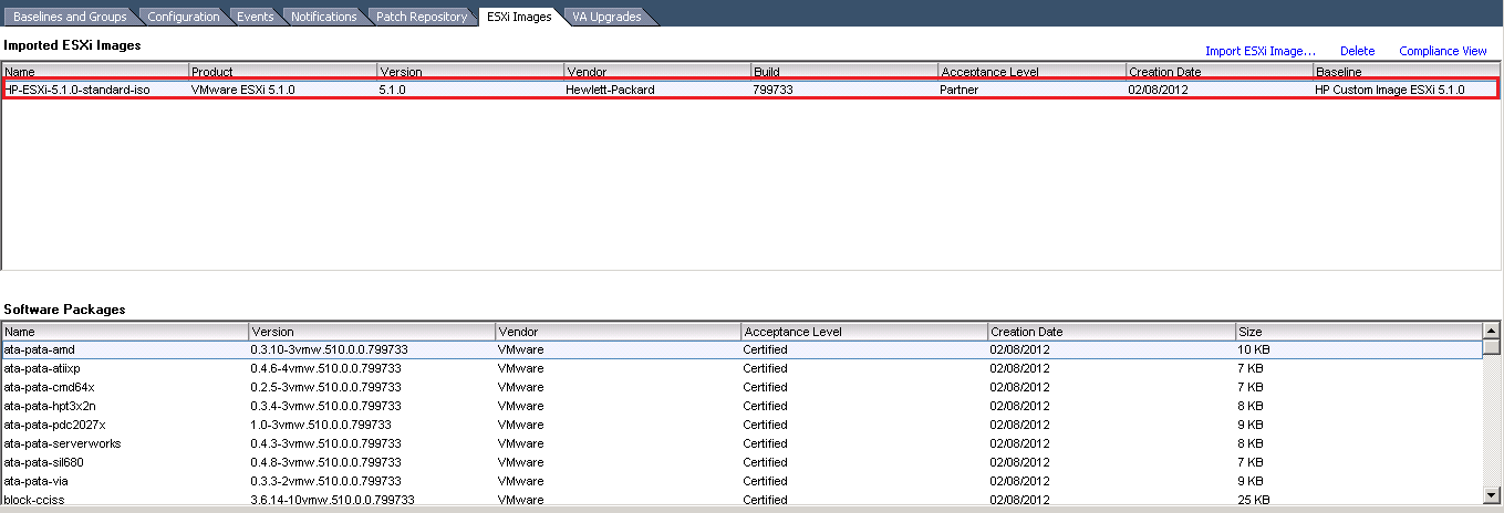
Fingers crossed you should see the Imported Image

ESXi Images 5

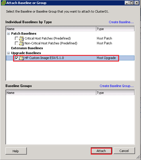
Next we are going to go the Hosts and Clusters View and select the Update Manager Tab and then select Attach

ESXi Images 6

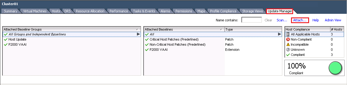
Select you Upgrade Baseline image and click Attach

ESXi Images 7

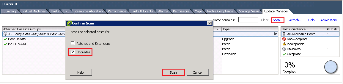
Next select Scan & choose Upgrades and then select Scan again

ESXi Images 8

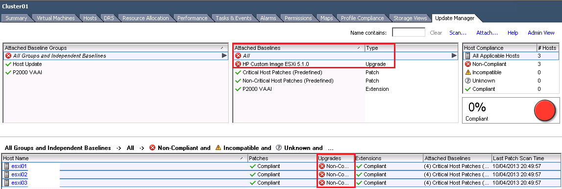
Suprisingly enough after the scan completes you will notice that your ESXi Hosts are no longer compliant

ESXi Images 9

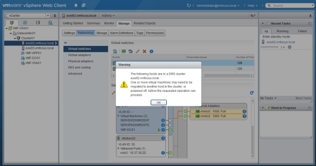
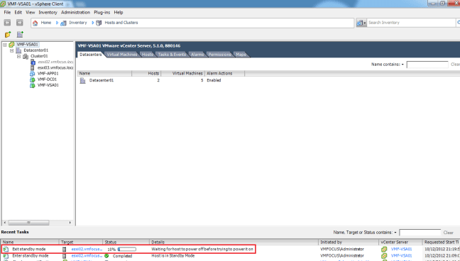
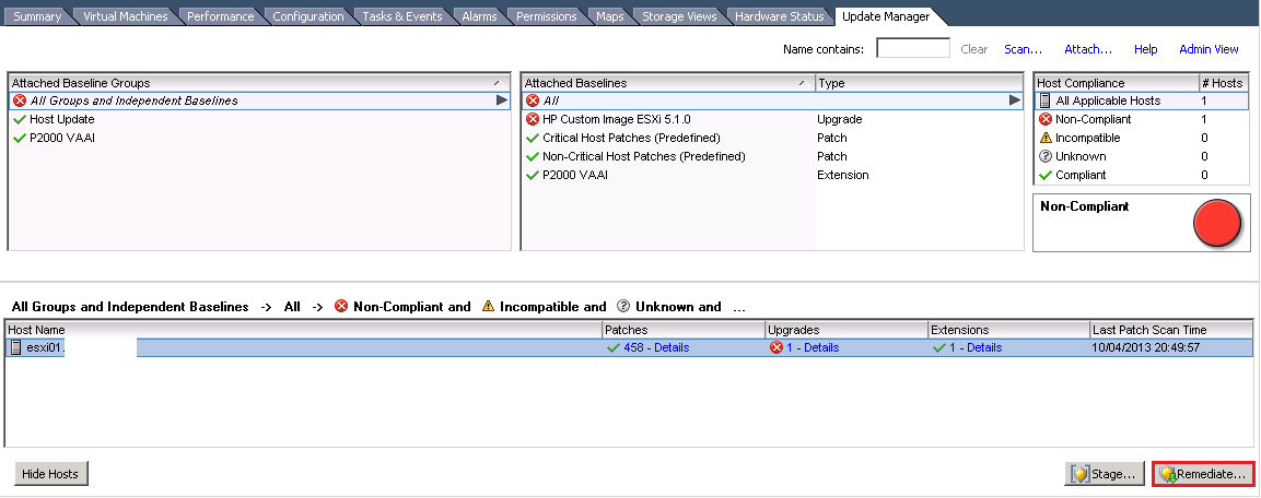
I tend to perform Baseline Upgrades on ESXi Hosts individual, rather than at Cluster level, just in case anything goes wrong.  With this in mind, go to your first ESXi Host and Select Remediate

Remediate 01

Select Upgrade Baseline and choose HP Custom Iage ESXi 5.1.0 and hit Next

Remediate 02

Accept the EULA and hit Next

Remediate 03

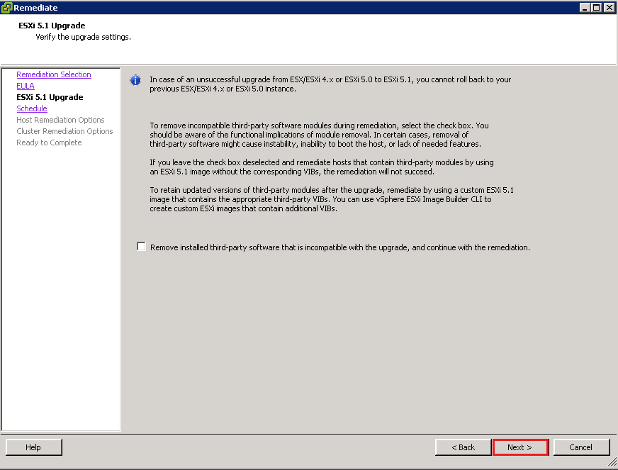
Woah, whats this message? ‘Remove installed third party software that is incompatible with the upgrade, and continue with remediation?  Word of warning you might want to check with your IT team to make sure that you aren’t going to lose any functionality.

Remediate 04

Enter a Task Name & Description and hit Next

Remediate 05

On the Host Remediation Options, make sure you tick ‘Disable any removable media devices connected to the virtual machines on the host’ as we don’t want an attached ISO to be the cause of our failure.  When you are ready hit Next

Remediate 06

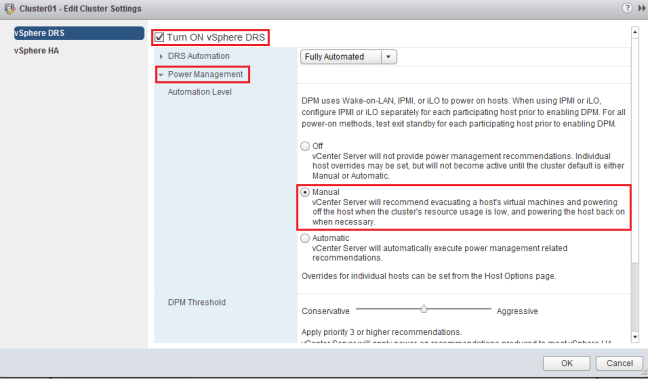
On the Cluster Remediation Options, I tend to make sure that DPM is disabled and also Admission Control so that the ESXi Host can actually be patched.  Then click Next

Remediate 07

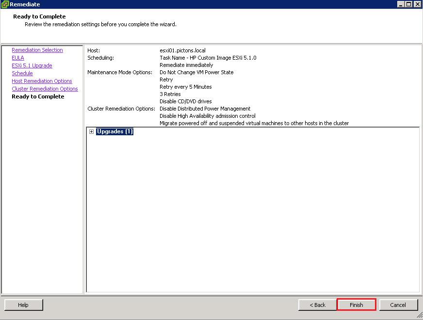
Once you are happy with your Upgrade Baseline, click Finish.  Time to go and make a brew as this is going to take along time!

Remediate 08

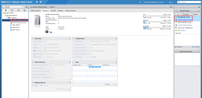
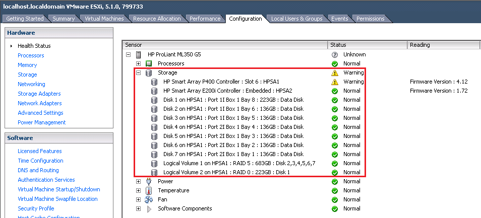
Awesome now that’s completed, we can see the Local Storage on the ESXi Host.

Storage View

Rinse and repeat for the rest of your ESXi Hosts.

Relay vCenter Alert Emails Externally

I was fortunate enough to have a second post published on the VMware SMB Blog site.  This particular post is an issue that I faced quite a while back, but it still holds true if you are trying to relay vCenter alerts externally.

From the Bloggers Bench: Relay vCenter Alert Emails Externally

When configuring your vCenter environment, most if not all VMware Administrators will set up email alerting. I covered the configuration of this in Setting Up & configuring Alarms In vCenter Part 1.

Unfortunately, if you leave Exchange 2010 using its Default Receive Connector, you will only receive alerts internally e.g. to the domains which Exchange 2010 is authoritative. This causes a problem if you need to send alerts to a third party e.g. Managed Service Provider.

To demonstrate the issue, I have connected to a vCenter server and then I’m going to telnet to an Exchange 2010 CAS Server on port 25 by issuing the command:

telnet VMF-EX01 25

Once in enter the following:

EHLO
MAIL FROM: vmware@testdomain.co.uk
<Press Enter>
RCPT TO: craig@vmfocus.com
<Press Enter>

Read more over at the VMware SMB Blog

How To Configure WOL ESXi5

Distributed Power Management is an excellent feature within ESXi5, it’s been around for a while and essentially migrates workloads to fewer hosts to enable the physical servers to be placed into standby mode when they aren’t being utilised.

Finance dudes like it as it saves ‘wonga’ and Marketing dudettes like it as it give ‘green credentials’.  Everyone’s a winner!

vCenter utilises IPMI, iLO and WOL to ‘take’ the physical server out of standby mode.  vCentre tries to use IPMI first, then iLO and lastly WOL.

I was configuring Distributed Power Management and thought I would see if a ‘how to’ existed and perhaps my  ‘Google magic’ was not working, as I couldn’t find a guide on configuring WOL with ESXi5.  So here it is, let’s crack on and get it configured.

Step 1

First things first, we need to check our BIOS supports WOL and enable it.  I use a couple of HP N40L Microservers and the good news is these bad boys do.

WOL Boot

Step 2

vCenter uses the vMotion network to send the ‘magic’ WOL packet.  So obviously you need to check that vMotion is working.  For the purposes of this how to, I’m going to assume you have this nailed.

Step 3

Check you switch config. Eh don’t you mean my vSwitch config Craig? Nope I mean your physical switch config.  The ports that your vMotion network plugs into need to be set to ‘Auto’ as for WOL to work the ‘magic’ with certain manufacturers this has to go over a 100Mbps network connection.

Switch

Step 4

Now we have checked our physical environment, let’s check our virtual environment.  Go to your ‘physical adapters’ to determine if WOL is supported.

This can be found in the vSphere Web Client (which I’m trying to use more) under Standard Networks > Hosts > ESXi02 > Manage > Networking > Physical Adapters

WOL 1

We can see that every adapter supports WOL except for vmnic1.

Step 5

So we need to check our vMotion network to ensure that vmnic1 isn’t being used.

Hop up to ‘virtual switches’ and check your config.  Good news is I’m using vmnic0 and vmnic2 so we are golden.

WOL 2

Step 6

Let’s enable Distributed Power Management. Head over to vCenter > Cluster > Manage > vSphere DRS > Edit and place a tick in Turn ON vSphere DRS and select Power Management.  But ensure that you set the Automation Level to Manual. We don’t want servers to be powered off which can’t come back on again!

WOL 3

Step 7

Time to test Distributed Power Management! Select your ESXi Host, choose Actions from the middle menu bar and select All vCenter Actions > Enter Standby Mode

WOL 4

Ah, we have a dialogue box appear saying ‘the requested operation may cause the cluster Cluster01 to violate its configured failover level for high availability.  Do you want to continue?’

The man from delmonte he says ‘yes’ we want to continue!  The reason for the message is my HA Admission Control is set to 50%, so invoking a Host shut down is violating this setting.

WOL 5

vCenter is rather cautious and quite rightly so.  Now it’s asking if we want to ‘move powered off and suspended virtual machines to other hosts in the cluster’.  I’m not going to place a tick in the box and will select Yes.

WOL 6

We have a Warning ‘one or more virtual machines may beed to be migrated to another host in the cluster, or powered off, before the requested operation can proceed’.  This makes perfect sense as we are invoking DPM, we need to migrate any VM’s onto another host.

WOL 7

A quick vMotion later, and we can now see that ESXi02 is entering Standby Mode

WOL 8

You might as well go make a cup of tea as it takes the vSphere Client an absolute age to figure out the host is in Standby Mode.

WOL 9

Step 8

Let’s power the host back up again.  Right Click your Host and Select Power On

WOL 10

Interestingly, we see the power on task running in the vSphere Web Client, however if you jump into the vSphere Client and check the recent tasks pane, you see that it mentions ‘waiting for host to power off before trying to power it on’

WOL 11

This had me puzzled for a minute and then I heard my HP N40L Microserver boot and all was good with the world.  So ignore this piece of information from vCenter.

Step 9

Boom our ESXi Host is back from Standby Mode

WOL 12

Rinse and repeat for your other ESXi Hosts and then set Distributed Power Management to Automated and you are good to go.

How To Change Default IOP Limit

After my last blog post, I realised I hadn’t actually walked you threw how to change the default IOP limit used by Round Robin.

To crack on and do this we need a SSH client such as Putty

Each change, only has to be made per Datastore which makes things a little easier.

SSH to your ESXi Host and enter your credentials.  We are going to run the command to give us the Network Address Authority names of our LUN’s.

esxcli storage nmp device list | grep naa

NAA 1

A quick look in the vSphere Web Client shows us which Datastores the NAA belong too.

NAA 2

In my case, I want to change the settings for all of the Datastores.  So we will start by checking the current multi path policy to ensure it’s set to Round Robin and the default IOP maximum limit.  Let’s run the following command:

esxcli storage nmp psp roundrobin deviceconfig get -d naa.6000eb3b4bb5b2440000000000000021

A bit like ‘Blue Peter’ here is one I did earlier! Not very helpful.

NAA 3

Let’s run the same command again but for a different NAA.

NAA 4

Excellent, to change the default maximum IOP limit to 1 enter this command

esxcli storage nmp psp roundrobin deviceconfig set -d naa.6000eb39c167fb82000000000000000c –iops 1 –type iops

To check, everything is ‘tickety boo’ enter

esxcli storage nmp device list | grep policy

You should see that each Datastore default maximum IOP limit is set at 1

NAA 5

Performance Increase? Changing Default IOP Maximum

I was reading Larry Smith JR’s blog post on Nexentastor over at El Retardo Land and I didn’t know that you could change the default maximum amount of IOPS used by Round Robin.

By default vSphere allows 1000 IOPS down each path before switching over to the next path.

Now, I wanted to test the default against 1 IOP down each path, to see if I could eek some more performance out of the vmfocus.com lab.

So before we do this, what’s our lab hardware?

ESXi Hosts

2 x HP N40L Microserver with 16GB RAM, Dual Core 1.5GHz CPU, 4 NICs

SAN

1 x HP ML115 G5 with 8GB RAM, Quad Core 2.2GHz CPU, 5 NICs

1 x 120GB OCZ Technology Vertex Plus, 2.5″ SSD, SATA II – 3Gb/s, Read 250M using onboard SATA Controller

Switch

1 x HP 1910 24G

And for good measure the software?

ESXi Hosts

2 x ESXi 5.1.0 Build 799733 using 2 x pNIC on Software iSCSI Initiator with iSCSI MPIO

1 x Windows Server 2008 R2 2GB RAM , 1 vCPU, 1 vNIC

SAN

1 x HP StoreVirtual VSA running SANiQ 9.5 with 4GB RAM, 2vCPU, 4 vNIC

Switch

1 x HP v1910 24G

Let’s dive straight into the testing shall we.

Test Setup

As I’m using a HP StoreVirtual VSA, we aren’t able to perform any NIC bonding, which in turn means we cannot setup any LACP on the HP v1910 24G switch.

So, you may ask the question why test this as surely to use all the bandwidth you need them to be in LACP mode.  Yep, I agree with you, however, I wanted to see if changing the IOP limit per path to 1, would actually make any difference in terms of performance.

I have created an SSD Volume on the HP StoreVirtual VSA which is ‘thin provisioned’.

Volume Details

From this I created a VMFS5 datastore in vSphere 5.1 called SSDVOL01.

Datastore

And set the MPIO policy to Round Robin.

MPIO

VMF-APP01 is acting as our test server and this has a 40GB ‘thinly provisioned’ HDD.

HDD

We are going to use IOMeter to test our performance using the parameters set out under vmktree.org/iometer/

Test 1

IOP Limit – 1000

SANiQ v9.5

Test 1

Test 2

IOP Limit – 1

SANiQ v9.5

Test 2

Test 1 v 2 Comparison

Test 1 Comparison

We can see that we get extra performance at the cost of higher latency.  Now let’s upgrade to SANiQ v10.0 AKA LeftHand OS 10.0 and perform the same tests again and see what results we get as HP claim it to be more efficient,

Test 3

IOP Limit – 1000

LeftHand OS10.0 (SANiQ v10.0)

Test 3

Test 1 v 3 Comparison

Test 1v3  Comparison

HP really have made the LeftHand OS 10.0 more efficient some very impressive results!

Test 4

IOP Limit – 1

LeftHand OS10.0 (SANiQ v10.0)

Test 4

Test 2 v 4 Comparison

Test 2v4 Comparison

Overall, higher latency for slightly better performance.

Test 1 v 4 Comparison

Test 1v4 Comparison

From our original configuration of a 1000 IOPS Limit per path and SANiQ 9.5.  It is clear that an upgrade to LeftHand OS10.0 is a must!

Conclusion

I think the results speak for themselves, I’m going to stick with the 1 IOP limit on LeftHand OS10.0 as even though the latency is higher, I’m getting a better return on my overall random IOPS.