Azure Site Recovery – What’s Coming Next?

AzureI’m sitting at London Heathrow Terminal 3 with a little bit of time on my hands before heading out to Virtualisation Field Day 6. So thought I would share a quick blog post around some news that I may have heard (cough) which are coming up in Azure Site Recovery.

  • Lower total cost of ownership using vSphere to Azure Site Recovery with a PaaS model
  • vSphere to Azure Site Recovery test failover support
  • vSphere to Azure Site Recovery integrated fast failback
  • vSphere to Azure Site Recovery compression support
  • vSphere to Azure Site Recovery preview portal integration, along with with RBAC and PowerShell
  • All failure scenarios enabled for the IaaS CSP model
  • SQL Always On Native Integration

Microsoft are knocking it out of the park with this upcoming update, the ability to perform a test failover and integrated fast failback are great steps in the right direction.

Failing Back From Azure Site Recovery: Part 3

In the previous blog post we initiated protection, now we are ready to failback to our on-premises vSphere environment.

Before we proceed with the failback, lets just to make sure everything is working correctly.  To do this launch vContinuum and select Manage Plans > Recover and then select your Plan (in my case VMFRP03).

Azure 78

Select Monitor and ensure that all green ticks are displayed in the Protection Plan Status window.

Azure 79

Lets move on! Select Manage Plans followed by Recover and then tick your Recovery Plan and finally hit Next

Azure 80

Before you run the recovery plan, I suggest you click Run Readiness Check and verify everything is OK.  In the example screenshot below you can see that my virtual machines haven’t finished replicating back to on-premises yet, so I need to wait a while.

Azure 81

After several cups of tea, we are now in a position where our ‘Run Readiness Check’ has been successful.  Let’s Click Next!Azure 83

Verify that you are happy with the network and hardware configuration and Click Next.

Azure 85

Finally, provide a Recovery Plan name and click Recover

Azure 86

When the Recovery Plan commences, you will see the Recovery Status window showing you the stages of the failback.

Azure 87

The failback process is fairly quick, once all the VM’s have been powered on we can verify the failback process.

Azure 88

vCenter Check

In vCenter we can see that the VM’s VMF-AZ01 and VMF-AZ02 have been powered on and have had VMware Tools Installed by checking the Task’s & Event’s Tab

Azure 89

We can also see that the on-premises Master Target no longer has extra hard drives added.  Note that the extra SCSI Controllers are still attached.

Azure 90

I also confirmed the IP Addresses match up to what was expected and that the credentials to login to the VM’s where maintained.

Azure Check

The original VM’s VMF-AZ01 and VMF-AZ02 are still running, these should be shutdown and deleted to avoid a split brain scenario.  I imagine the reason for keeping this is in case anything goes wrong with the failback to on-premises you have a fall back position.

Azure 91

Once the VM’s have been deleted, I also recommend checking your Recovery Plans and Protection Groups and deleting these to avoid any confusion.

Final Thoughts

Azure Site Recovery is a good product which is fairly straight forward to configure and use.  I’m sure that in future versions that failback will be slightly more elegant.

Failing Back From Azure Site Recovery: Part 2

In the previous blog post we performed the initial installation for failing back to on-premises vSphere.  Now it’s time to configure our on-premises Master Target Server.

Login to your on-premises Master Target Server and launch vContinuum.  Change the Application Type to P2V (this is how vContinuum sees Azure VM’s) and select new Protection

Azure 66

Select your Azure Virtual Machines.

Azure 67

If you have performed several failovers and failbacks (like I have) you will be greeted with a remove duplicate entries dialogue box.Azure 68

Azure Site Recovery uses the context of ‘Host ID’.  To identify which entry should be kept, login to your protected VM and go to C:Program Files (x86)Microsoft Azure Site RecoveryApplication Dataetc and open the file drscout.conf using notepad.  Locate the Host ID and remove all other entries from the duplicated entries screen.

Azure 69

Click Next and enter the following details:

  • vCenter Name
  • Username
  • Password

Then select Get Details and select the your Master Target Server and Click Next

Azure 70

I have chosen the following settings:

  • Retention Size – Size of log disk E Drive.
  • Retention Value – Up to 2 logs of 100MB will be stored
  • Days or Hours – Logs will be stored for up to 2 days
  • Consistency Interval – Replication interval will be checked every 15 minutes to ensure it is in line with this target
  • Datastore – Target datastore

Azure 71

Next onto the network settings, these are pretty straight forward:

  • Network Configuration – Select IP Address and Port Group the VM should be attached to on failback
  • Hardware Configuration – CPU and Memory the VM will have when failed back
  • Display Name – Hope I don’t have to explain this
  • NAT Configuration – This is how each item communicates with each other.  A little more details below.

Use PS NAT IP between source and process server for data transfer – This is between the Azure Protected VM and the Process Server.  If they are on the same Azure subnet then this can be left blank.  If on different subnets then tick the box.

Use PS NAT IP between process server and target for data transfer – This is between the Azure Process Server and our on-premises Master Target.  If they are on the same subnet or using a Site to Site VPN this can be left blank.  If transfering data over the public internet via SSL then tick the box.

Azure 72

Note: If using PS NAT IP between Azure Process Server and target for data transfer you will need to enter the public IP address of the Azure Process Server under ‘Update PS NAT IP(s)’

Azure 73

Now we are ready to run the ‘Readiness Check’.  Figures crossed it goes smoothly.  Click ‘Run Readiness Checks’

Azure 74

If you pass correctly you should be in a position to create a New Failback Plan.  Enter a name and Click Protect

Azure 75

The Protection Status window is displayed which shows the steps which are being performed.

Azure 76

Final Thought

At the moment, it is a manual process to update the IP Address and hardware configuration from Azure to on on-premises.  It would be great if the Azure team could introduce:

  • A bulk subnet change for example every VM on 192.168.3.0/24 in Azure should go to 10.3.1.0/24 on premises with a default gateway of 10.3.2.1254 and DNS Servers 10.3.1.1
  • A bulk hardware change by grouping VM’s for example tick a group of VM’s and they have 2 vCPU and 4GB RAM

In the next blog post we will perform the failback to our on-premises vSphere environment.


Failing Back From Azure Site Recovery: Part 1

In the last blog post we covered failing over to Azure.  Let’s take a moment to be honest, Microsoft want you to stay in Azure when you have failed over.  However for some customers this isn’t going to be a reality and they will want to move back to their on-premises vSphere environment.

So in this blog post we are going to failback to our on-premises vSphere environment.  Before we start we need to look at the architecture to ensure that we understand how it fits together.

Components of Azure Site Recovery (Failback to vSphere)

  • Azure Process Server – This receives replication data from the Mobility Service (in-guest agent)  using disk based cache.  It is used to compress and encrypt data on-premises before sending it over internet/VPN/Express Route to the Master Target Server on-premises
  • Azure Mobility Service – This can be pushed out automatically by the Process Server or performed manually.  Essentially it is an IO splitter that takes a write to disk, holds it in memory and sends it across to the Azure Process Server
  • Azure Configuration Server – This is the brains, it co-ordinates communication between all components both on-premises and in Azure.  Each Configuration Server can support up to 100 source virtual machines.
  • On-Premises Master Target – Receives incoming replication traffic from the Azure Process Server. Each protected VM is added as a VMDK.
  • On-Premises vContinuum Server – Performs the management and configuration of the failback from Azure to vSphere.

The diagram below shows the relationship between all the components.Azure Site Recovery Components Failbackv0.1

As you have probably guessed, we have a couple of servers that need to be deployed onto our on-premises vSphere infrastructure which are the vContinuum Server and Master Target Server.

The requirements for the vContinuum Server and Master Target Server are shown below:

  • Master Target Server – Windows Server 2012 R2, 8 Cores, 14GB RAM and at least 600GB HD
  • vContinuum Server – Windows Server 2012 R2, 8 Cores, 8GB RAM and at least 160GB HDD

On-Premises vContinuum Server Installation

Log onto your vContinuum Server and download the vContinuum software from here.  You should be greeted by a download prompt for ‘Microsoft-ASR_vContinuum_MT_8.4.0.0_Windows_GA_28Jul2015_release.exe’.

Launch the .exe and Click Next

Azure 59

If you haven’t already download and installed vSphere CLI.  Instructions on how to do this are covered in this blog post.

Next we need to enter the following information:

  • Configuration Server IP Address
  • Configuration Server Port
  • Configuration Server Passphrase

This blog post covers details on how to obtain this information.

Azure 60

Click Install

Azure 61

This can take a while so suggest you head off and grab a cup of tea.  Once completed select Yes to restart your computer.

Azure 62

On-Premises Master Target Server Installation

Before installing your Master Target Server, it is recommended to have a secondary SCSI Controller and Hard Disk for your Retention Drive.Azure 63

The installation for the Master Target is included in the vContinuum .exe.  So the procedure is exactly the same as the vContinuum Server installation.

Azure Process Server

Next we need to ensure that we have a Process Server available in Azure so that it can send data to the Master Target Server on-premises.

Login to the Azure Portal and select Recovery Services > VMFocusVault > Servers > Configuration Servers > + Process Server

Azure 64

Enter the details for:

  • Process Server Name
  • User Name
  • Password
  • Configuration Server
  • Azure Network
  • IP Address

Azure 64

Once deployed login to your Azure Process Server enter the details for your configuration server and Click Save

Azure 65

Note: It is recommended to deploy your Azure Process Server on the same network as your Azure Configuration Server

Now that the initial installation is done we are ready to start configuring failback in the next blog post.

Failing Over To Azure Site Recovery

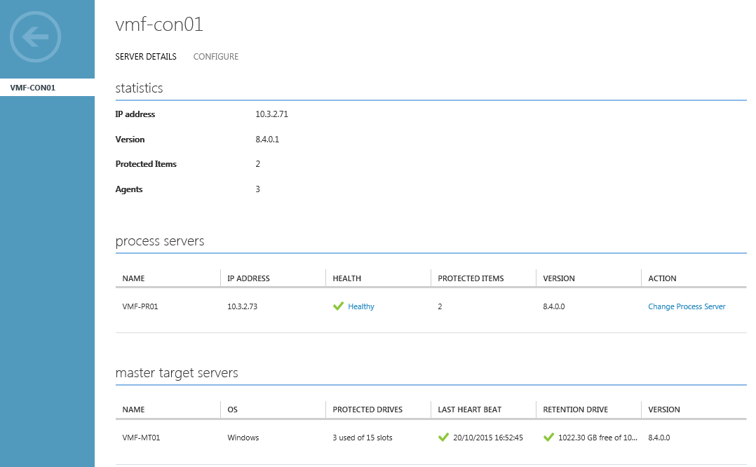
We are ready to failover our on-premises vSphere virtual machines to Azure.  Before we do it’s important to verify that our Configuration Server and Master Target Server are functioning correctly.

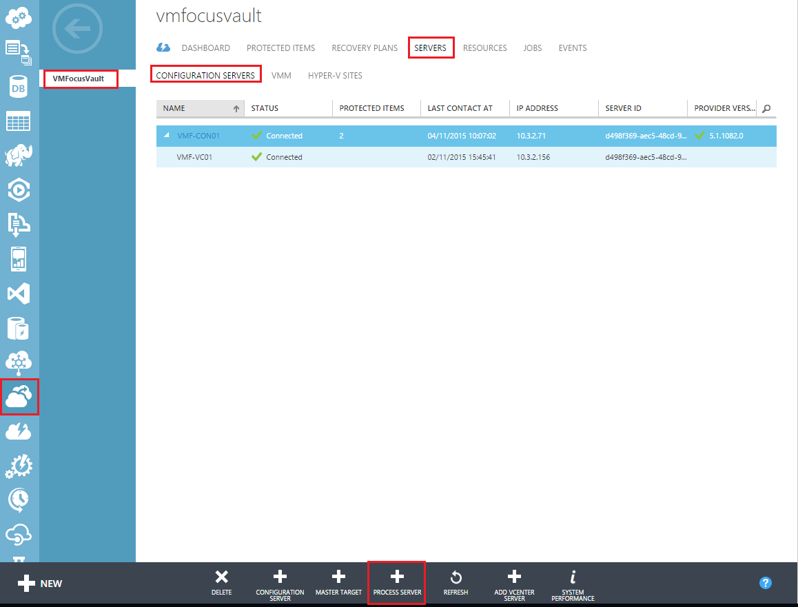
In the Azure Portal, select Recovery Services > VMFocusVault > Servers > Configuration Servers > Select Configuration Server.  Verify that displayed details are healthy.

Azure 46

Before we proceed any further, it’s worthwhile noting that Azure Site Recovery is in it’s infancy from an on-premises vSphere to Azure perspective.  Therefore it’s worthwhile noting that:

  • Only unplanned failover is supported
  • If you want your data to be consistent, shutdown your protected VM’s on-premises and wait for the next replication interval to complete

We need to create a Recovery Plan (which I would expect you to have in place already).  The purpose of a Recovery Plan is to group together virtual machines which should failover together.

  • Virtual Machines across different Protection Groups can be in the same Recovery Plan.  The use case for this is perhaps you have a three tier application where VM1 RPO is daily, VM2 PPO is 4 Hourly and VM3 is Hourly.
  • Once in a Recovery Plan, virtual machine start up order can be determined
  • Before a virtual machine is started a manual action can be inserted e.g. prompt to verify that a service has been checked before moving onto the next step
  • Before or after a virtual machines is started a script can be triggered

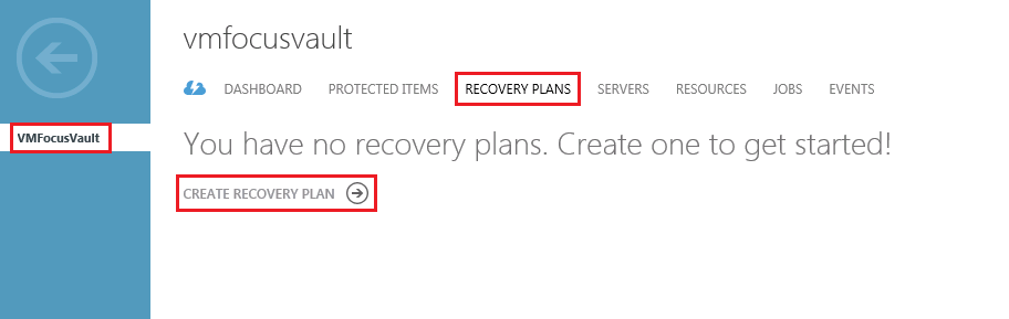
To create a Recovery Plan select Recovery Services > VMFocusVault > Recovery Plans > Create Recovery Plan

Azure 47

I’m going to create a single Recovery Plans called VMF-RP01:

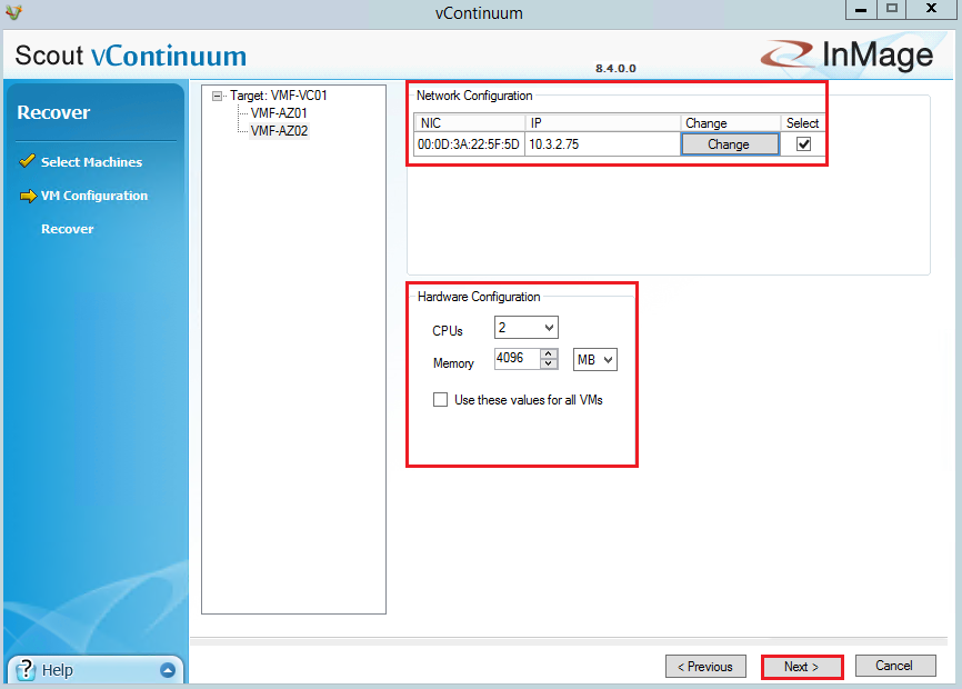
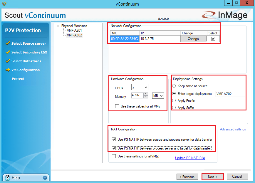
  • Virtual machine VMF-AZ01 needs to maintain it’s current IP address, as if I had stretched my on-premises layer 2 network into Azure
  • Virtual machine VMF-AZ02 need a new IP address and therefore will be RE-IP’d as part of this process
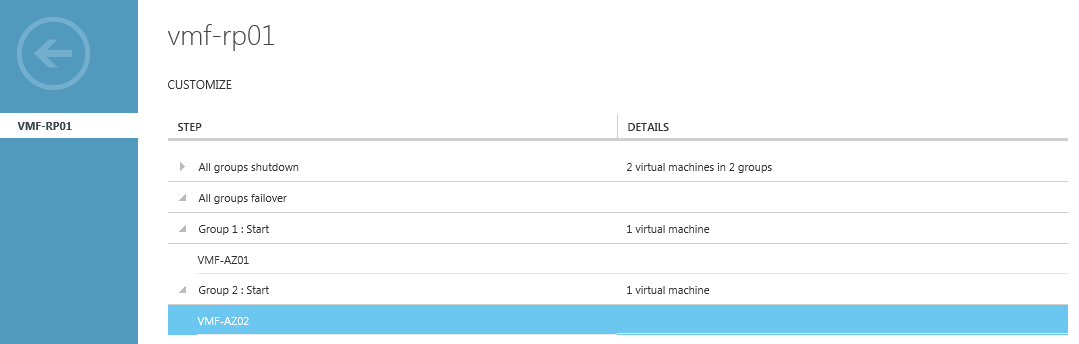
  • VMF-AZ01 needs to start before VMF-AZ02

The screenshot below confirms the name of the Recovery Plan I have created called VMF-RP01.

Azure 48

As described the Protected Entities are VMF-AZ01 and VMF-AZ02.

Azure 49

Once the Recovery Plan is created.   Select the it by clicking on it’s name (in my case VMF-RP01) and you will see the following screen.

Azure 50

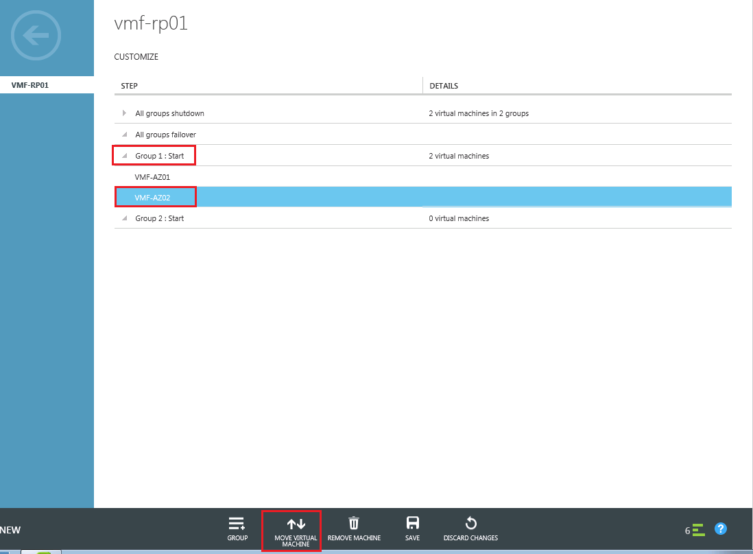
By default all VM’s will be started and stopped at the same time. To change this select the Group+ icon and you will see a Group 2 has been created.

Azure 51

Expand Group 1 and Select VMF-AZ02 and Select Move Virtual Machine > Group 2

Azure 52

Once done it should look like this

Azure 53

Note: Don’t forget to save your changes to the Recovery Plan

Failover

Time to failover, to test things properly, I’m going to mimic an actual disaster in which our on-premises virtual machines are unable to communicate with Azure Site Recovery.  The easiest way for us to do this is to disable the virtual NICs on our on-premises Process Server, VMF-AZ01 and VMF-AZ02 in vCenter.

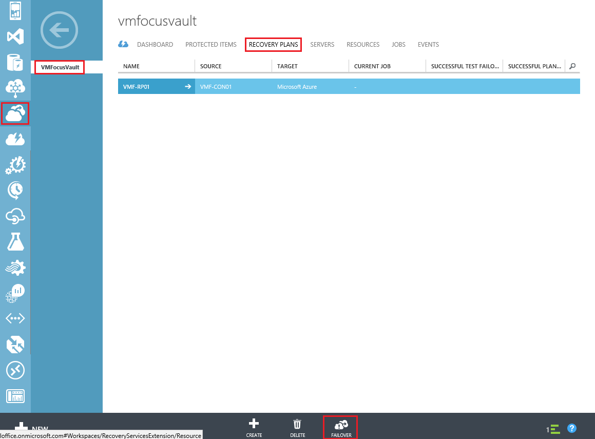
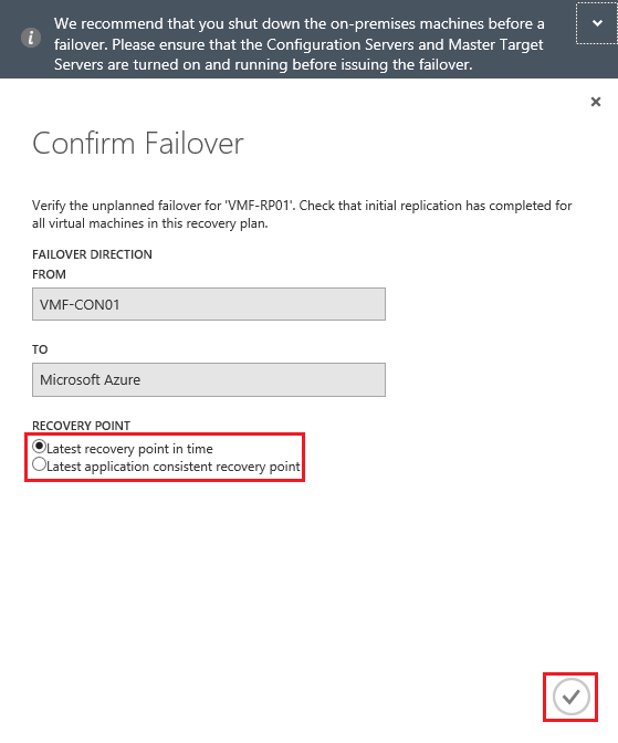
Back to the Azure Portal, Select Recovery Services > VMFocusVault> Recovery Plans > Failover

Azure 54

Select either Latest Recovery Point In Time or Latest Application Consistent Recovery Point

Azure 55

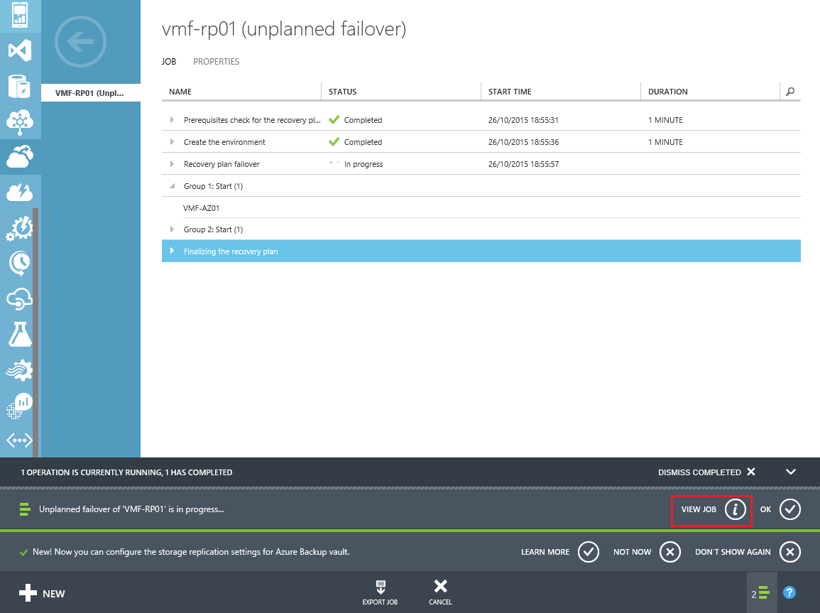
That’s it sit back and make a cup of tea whilst our Recovery Plan goes into full effect.  If however, you do want to monitor the Job, select View Job.

Azure 56

In total VMF-RP01 took 24 minutes to complete.Azure 57

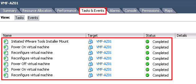
We should now see two more virtual machine instances available.

Azure 58

Checking the virtual machines, I can verify the following:

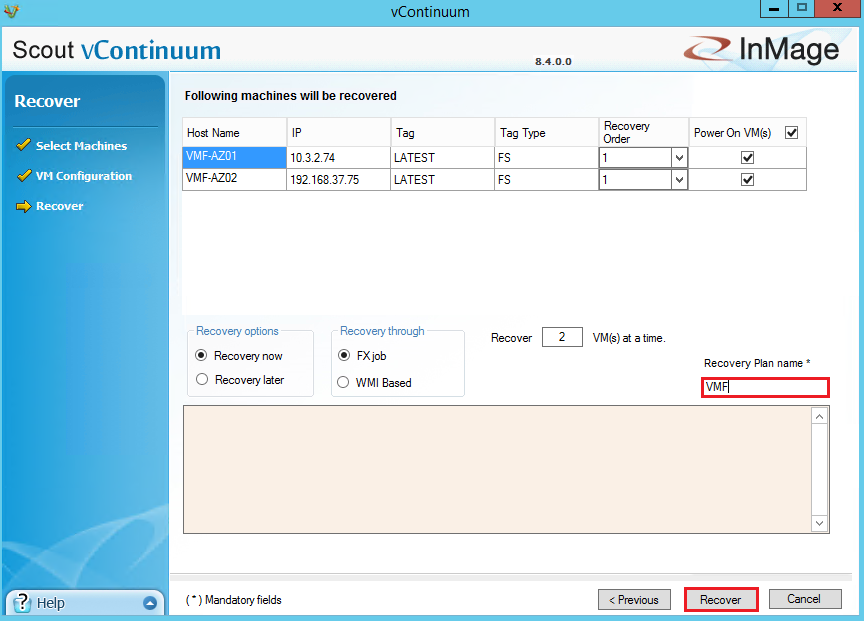
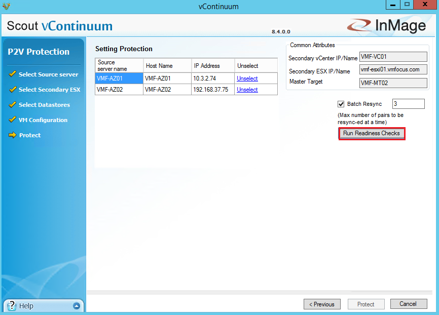
  • VMF-AZ01 is on IP Address 10.3.2.74 which is our extended on-premises Layer 2 network
  • VMF-AZ02 is on IP Address 192.168.37.75 which is our routed Layer 3 network

Interestingly, EndPoints  aren’t configured for RDP and PowerShell as per a standard virtual machine deployed in Azure.  External access if required, will need to be configured manually.

Azure 58

In the next blog post, we are going to reprotect and failback to on-premises.