The HP StoreVirtual VSA is sheer awesomeness. It’s going to form the basis of all my storage for my home lab.
Before we move on, let’s examine why it’s so cool.
- Runs as a VM on either Hyper V, ESXi or VMware Player
- Use existing HP ProLiant or C Class Blade hardware to create a virtual iSCSI SAN.
- Thin Provisioning
- Storage Clustering
- Wide Strip RAID 5, 6 and 10
- Network RAID 0, 5, 6, 10, 10+1 and 10+2
- Automatic SAN Failover using Failover Manager
- A Synchronous Replication including bandwidth throttling
That’s a large amount of features which is perfect for any lab environment, it will give me the ability to create a vSphere Metro Storage Cluster, deploy Site Recovery Manager as it has a Storage Replication Adapter and is featured on the SRM Hardware Compatibility List
The hardware requirements to run the HP StoreVirtual VSA are:
- 1 x 2GHz CPU (reserved)
- 3GB RAM (reserved)
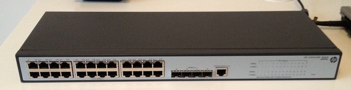
- Gigabit Switch
Lab Storage Architecture
So what will be the architecture for my VSA? Well the physical server is a HP ProLiant ML115 G5 with the following specifications:
- 1 x AMD Quad Core CPU 2.2GHz
- 5 x 1 GB NIC’s
- 2 x 120GB SSD
- 2 x 500FB 7.2K SATA
The HP ProLiant ML115 G5 boots ESXi5 from USB. Screenshot below from VMware.

You may be questioning, if I’m going to use hardware RAID on the HP ML115 G5? Well the simple answer is no. I guess you are now thinking you are crazy, why would you do that? Well there is method to my madness.
Step 1 We have four hard drives in total, let’s call them SATAHDD01, SATAHDD02, SSDHDD01 and SSDHDD02.
Step 2 Create a Datastore called SATAiSCSI01 on SATAHDD01 using all the available space and install the SATAVSA01 onto this.
Step 3 Create a Datastore called SSDiSCSI01 on SSDHDD01 using all the available space and install the SSDVSA01 onto this.
Step 4 Create a Datastore called SATAiSCSI02 on SATAHDD02 using all the available space and install the SATAVSA02 onto this.
Step 5 Create a Datastore called SSDiSCSI02 on SSDHDD02 using all the available space and install the SSDVSA02 onto this.
Step 6 We configure SATAVSA01 and SATAVSA02 in Network RAID 10 giving us a highly available SATA clustered solution.
Step 7 We configure SSDVSA01 and SSDVSA02 in Network RAID 10 giving us a highly available SSD clustered solution.
This probably sounds a little complicated, I think in this situation a diagram is in order!

Cool, so without further delay, let’s start installing and configuring.
Installing HP StoreVirtual VSA
We need to download the software from here. You will need to register for a HP Passport Sign in to obtain the software which is a quick and easy process.
Once we get to the download page you will get three choices, the one we want to select is ‘HP P4000 VSA 9.5 Full Evaluation SW for VMware ESX required ESX servers (AX696-10536.zip)

Time to stick the kettle on for a fresh brew, unless you have a faster broadband connection than me!
Once downloaded, extract the files to a location on your laptop/desktop and fire up vSphere Client and connect to vCenter or your ESXi Host.
You would think that’s it, time to deploy the OVF, nope. We need to browse into the extracted files until we get to HP_P4000_VSA_9.5_Full_Evaluation_SW_for_Vmware_ESX_requires_ESX_servers_AX696-10536Virtual_SAN_Appliance_TrialVirtual_SAN_Appliance and click autorun.exe
This will launch the a further self extractor so that you can either deploy the HP StoreVirtual VSA via an OVF or connect directlty to an ESXi Host or vCenter using HP’s software.
Accept the License Agreement > Select Install VSA for VMware ESX Server and choose a further directory to extract the files too.

Once done, you will get a CMD prompt asking if you want to run the Virtual SAN Appliance installer for ESX? In this instance we are going to close down this dialog box as if we use the GUI to connect to an ESXi 5.1 host it won’t pass validation.
Instead we are going to deploy it as an OVF.
So first things first, we need to create Datastore called SATAiSCSI01 which will contain the HP StoreVirtual VSA OVF virtual HDD. I’m assuming you know how to do this so we will move onto deploying the OVF. To do this click File from the vSphere Client > Deploy OVF Template.

Browse to the location ending in VSA_OVF_9.5.00.1215VSA.ovf and click Next

Click Next on the OVF Template Details screen and Accept the EULA followed by Next. Give the OVF a Name in this case HPVSA01 and click Next. I would recommend deploying the Disk Format as Thick Provision Eager Zeroed and clicking Next. Next up choose a Network Mapping and click Finish.
Top Tip, don’t worry if you cannot select the correct network mapping during deployment. Edit the VM settings and change it manually before powering it on.
If all is going well you should see a ‘Deploying SATAVSA01’ pop up box.

On my physical vSphere 5.1 host, I have five NIC’s. In this configuration we are going to assign one physical NIC to the management network and four physical NIC’s to the iSCSI network. Hang on a minute Craig, why aren’t you using two physical NIC’s for the management network? Well first of all this is my home lab and I can easily connect to the HP Central Management Server using the iSCSI Port Group on a VM or if I create an Access Control List on my HP v1910 I can access SATAVSA01, SATAVSA02, SSDVSA01 and SSDVSA02 from the Management network . Therefore I have chosen to give resiliency and bandwidth to the HP StoreVirtual VSA iSCSI connections.
This actually ties in quite well with the HP StoreVirtual best practice white paper which states you should use two vNIC’s per VSA. So when we are finished we will have:
- SATAVSA01 with 2 x vNIC’s
- SATAVSA02 with 2 x vNICs
- SSDVSA01 with 2 x vNICs
- SSDVSA02 with 2 x vNICs

vSphere will automatically load balance the VM’s (SATAVSA01, SATAVSA02, SSDVSA01 and SSDVSA02) onto different physical NIC’s. If you want to check this you can use ESXTOP which I covered in this blog post.
![]()
Cool, so we now have the HP StoreVirtual VSA with some virtual NIC’s, but we have no hard disk capacity. We are going to edit SATAVSA01 settings and click add Hard Disk > Create A New Virtual Disk > Next .
We now have a choice on the Disk Provisioning, which one do we go for?
Thick Provision Lazy Zeroed Space is allocated by ESXi however the zero’s are not written to the underlying hard disk until that space is required to be used. Meaning that we have an overhead, do we want this for our iSCSI SAN?
Thick Provision Eager Zeroed Space is allocated by ESXi and all zero’s are written. The best choice!
Thin Provision Limited space is allocated by ESXi and will automatically inflate when needed, again zero’s are not written to the underlying hard disk until that space is required to be used. Meaning that we have an overhead, do we want this for our iSCSI SAN?
In my case I have gone with the following settings.

On the Advanced Options screen we need to change the Virtual Device Node to SCSI (1:0) otherwise the hard drive space won’t be seen by the HP StoreVirtual VSA.

Click finish, this time you will definitely be able to make a brew whilst we wait for vSphere to provision the hard disk.
Lastly, we need to repeat this process for SATAVSA02, SSDVSA01 and SSDVSA02.
In the next blog post I promise we will start to power things on!