How To Configure Access Lists & Route Between VLAN’s On HP v1910 24G

In the previous how to, we configured layer 3 static routes and VLAN’s on the HP v1910 24G you will have noticed that all traffic can pass between VLAN’s without any restrictions.  So why is this happening?

Well the answer is because we have turned on routing by giving an IP Address to each VLAN.  This means the HP v1910 uses it’s own routing table to send traffic from VLAN 1 to VLAN 10.

Let’s test this.  My laptop sits on VLAN 1 on IP Address 192.168.37.152 using the HP v1910G as it’s default gateway on 192.168.37.221

VLAN 1

I have five VLAN Interfaces created which can be found under Network > VLAN Interface > Summary

VLAN 2

Behind VLAN 10 is a device with IP Address 10.37.10.11, which I can ping

VLAN 3

Next, I’m going to remove the VLAN Interface for VLAN 10

VLAN 4

Don’t worry, the VLAN is still in play, we just have removed the ability to route between subnets.  Now if we ping the same device we get an epic fail.

VLAN 5

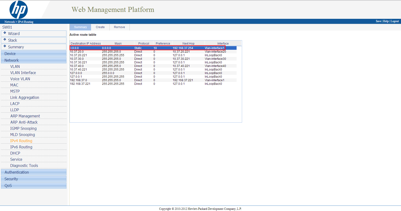
Notice we get a reply from 192.168.37.254 which isn’t an VLAN IP Address.  The reason for this is that 192.168.37.254 is the default gateway for our HP v1910G.  The HP v1910G is saying I haven’t got a clue how to get to 10.37.10.11, so let me send that traffic to my default gateway 192.168.37.254.

VLAN 6

My firewall which is on 192.168.37.254 has a static route to 10.37.10.0 255.255.255.0 via 192.168.37.221 (VLAN 1 Interface on HP v1910G).  When the HP v1910G receives the packet, it drops it as has no where to send the ICMP request.

So just to reiterate, that when we have an VLAN Interface, the HP v1910G will be able to route all traffic between VLAN’s, unless we do something about it.

Access Lists

This is where the Access List comes into play, an Access List specifies what source traffic is allowed to get to what destination traffic.  Think of it as being in a hallway in a house and all the doors are locked.  You then get given a key and you can get from the hallway into the lounge.  The source is the hallway, the destination is the lounge and the key is the Access List.

So before we move any further, I want to give you a brief explanation of what I want to be able to achieve.

My laptop resides on 192.168.37.152/24 on VLAN 1 and I want to be able to connect to my HP StoreVirtual VSA which is on 10.37.20.1/24 VLAN 20.

I also have a Windows 7 machine on 10.37.20.211/24 VLAN 20.

I want to be able to get from my laptop to 10.37.20.1, but I don’t want to let any other traffic threw.

Let’s run a ping to both devices, you can see that I have connectivity to both 10.37.20.1 HP StoreVirtual VSA and 10.37.20.221 Windows 7.

VLAN 7

So let’s create an Access List to do something about this.

Creating An Access List

We need to go to QoS from the left hand menu then onto ACL IPv4

Next we want to select Create

Now we have a choice from Basic ACL’s, Advanced ACL’s and Ethernet Frame Header ACL’s.  OK what are the differences?

Basic ACL these only match source IPv4 address’s

Advanced ACL these match source and destination IPv4 address’s and also protocols on different port numbers e.g. TCP 80

Ethernet Frame Header ACL these match source and destination MAC addresses

With this is in mind, we are going to use Advanced ACL’s as we want to match interesting traffic from source to destination.

In the ACL Number section, type in 3001 and we want the match order to be Config and click Apply

You will see the ACL Number appear in the bottom table, notice we have no rules applied against it yet.

Next we want to go onto the Advanced Setup Tab at the top.  We are going to enter the following information:

  • ACL > Select 3001
  • Rule ID > Select and Enter 10
  • Action > Permit
  • Source IP Address > 192.168.37.152
  • Source Wildcard > 0.0.0.0
  • Destination IP Address > 10.37.20.1
  • Destination Wildcard > 0.0.0.0
  • Protocol > IP
  • Click Add

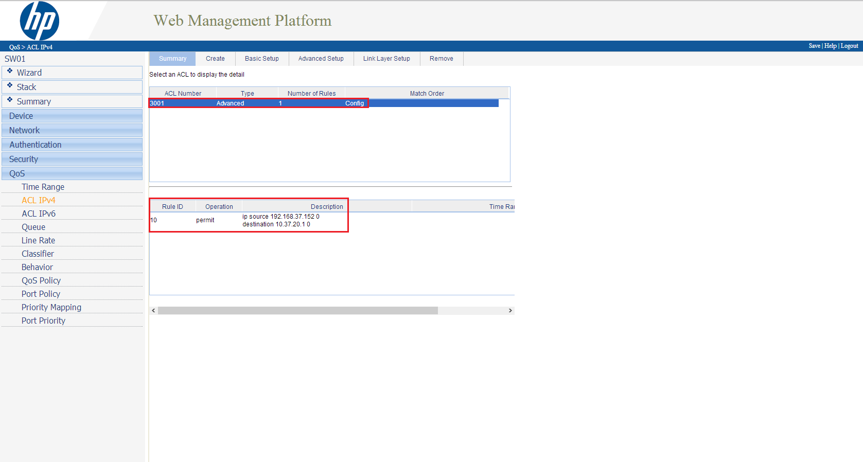
Now when you click on the Summary Tab you should see your rule in place!

VLAN 8

I want to back track slightly on some of the entries we made into the Advanced ACL, to make sure you are clear on what we did.

Rule ID this is the order in which the rules are read we entered in number 10, so this rule is read first, if you added a rule ID 9 this would get read before rule ID 10.

Wildcard this is the reverse of a normal subnet mask e.g. 255.255.255.0 becomes 0.0.0.255

TOP TIP: At the end of every Access List is always a silent deny, which means you don’t see the traffic being dropped it just happens!

Let’s see if it works shall we? Let’s ping from my laptop to a HP StoreVirtual VSA 10.37.20.1 success, what about the Windows 7 on 10.37.20.211, err also success, that’s not right!

VLAN 7

So what the heck is going on? Well as we haven’t applied the ACL3001 to an interface, everything carries on as per normal.

To be honest, applying an Access List to an interface on the HP v1910G is a royal pain.  For most switches you just choose to apply the ACL to an interface either inbound or outbound.  However, on the HP v1910G you have to perform the following:

  • Create a QoS Classifier
  • Create a QoS Behavior
  • Create a QoS Policy using the QoS Classifier and QoS Behavior
  • Apply the QoS Policy to a Port

I’m not going to run through how to do this, as examples can be found in the HP v1910G Manual page 465.

P4000: An Error Occurred While Reading The Upgrade Configuration File

With any device, it is important to keep up to date with the latest firmware the vendor can offer.

I always check the manufactures websites on a monthly basis to see if anything is new,  with this in mind, I was trying to update my P4000 StoreVirtual VSA today and I kept getting the following error message:

‘An error occurred while reading the upgrade configuration file.  If the file was from a web connection, click Try Download Again, otherwise recreate your media image’.

A quick check in Help > Preferences > Upgrades I saw that the Download Directory location didn’t look quite right.

So I entered a at the end of the Download Directory location

Clicked on OK and started the download again, voila this time it worked!

Part 3 – Automating HP StoreVirtual VSA Failover

In part two we installed and configured HP StoreVirtual VSA on vSphere 5.1 in this blog post we are going to look at automating failover.

I think a quick recap is in order.  If you remember we received a warning when adding SATAVSA01 and SATAVSA02 to the Management Group SATAMG01.  Which was:

‘to continue without installing a FOM, select the checkbox below acknowledging that a FOM is required to provide the highest level of data availability for a 2 storage system management group configuration. Then click next’.

This error message is about quorum, a term that I’m sure alot of you are familiar with when working with Windows clusters.  Each VSA run’s whats known as a ‘manager’ which is really a vote.  When we have two VSA’s we have two votes, which is a tie.  Let’s say that one VSA has an issue and goes down, how does the the remaining VSA know that? Well it doesn’t.  It could be that both VSA’s are up and they have lost’s the network between them.  This then result’s in split brain scenario.

This is where the Failover Manager comes into play.  So what exactly is a Failover Manager? Well it’s specialized version of the SAN/iQ software which runs under ESXi, VMware Player or the elephant in the room (Hyper V).  It’s purpose in life is to be a ‘manager’ and maintain quorum by introducing a third vote ensuring access to volumes in the event of a StoreVirtual VSA failure.  The Failover Manager is downloaded as an OVF and the good news is we already have a copy which we have extracted.

A few things to note about the Failover Manager.

  • Do not install the Failover Manager on a StoreVirtual VSA you want to protect,as if you have a failure the Failover Manager will loose connection.
  • Ideally it should be installed at a third physical site.
  • Bandwidth requirements to the Failover Manager should be 100 Mb/s
  • Round trip time to the Failover Manager should be no more than 50ms

In this environment we will be installing the Failover Manager on the local storage of ESXi02 and placing it into a third logical subnet.  I think a diagram and a reminder of the subnets are in order.

Right then, let’s crack on shall we.

Installing Failover Manager

We are going to deploy SATAFOM onto ESXi02 local hard drive which is called ESXi02HDD (I should get an award for my naming conventions).

The Failover Manager or FOM from now on, is an OVF so we need to deploy it from vSphere Client.  To do this click File > Deploy OVF Template.

Browse to the location of your extracted HP StoreVirtual VSA files ending in FOM_OVF_9.5.00.1215FOM.ovf

Click Next on the OVF Template Details screen and Accept the EULA followed by Next.  Give the OVF a Name in this case SATAFOM and click Next.  When you get to the storage section you need to select the local storage on a ESXi Host which is NOT running your StoreVirtual VSA.  In this case it is ESXi02HDD

Click next and select your Network Mapping and click Finish.

TOP TIP, don’t worry if you cannot select the correct network mapping during deployment. Edit the VM settings and change it manually before powering it on.

If all is going well you should see a ‘Deploying SATAFOM′ pop up box.

Whilst the FOM is deploying let’s talk networking for a minute.

On ESXi02, I have a subnet called FOM which is on VLAN 40.  We are going to pop the vNIC;s of SATAFOM into this.  The HP v1910 24G is the layer three default gateway between all the subnets and is configured with VLAN Access Lists to allow the traffic to pass (I will do a VLAN Access List blog in the future!)

Awesome let’s power the badboy on.

We need to use use the same procedure we used to set the IP address’s on the FOM as we did on the VSA.  Hopefully you should be cool with this, but if you need a helping hand refer back to How To Install & Configure HP StoreVirtual VSA On vSphere 5.1

The IP address’s I’m using are:

  • eth0 – 10.37.40.1
  • eth1 – 10.37.40.2

Failover Manager Configfuration

Time to fire up the HP Centralized Management Console (CMC) and add the IP Address into  Find Systems.

Log into view SATAFOM and it should appear as follows.

Let’s Rich Click SATAFOM and ‘Add to an Existing Management Group’ SATAMG01

Crap, Craig that didn’t work, I got a popup about a Virtual Manager. What’s that all about?

Nows a good time as any to talk about two other ways to failover the StoreVirtual VSA.

Virtual Manager this is automatically added to a Management Group that contains an even number of StoreVirtual VSA’s.  If in the event you have a VSA failure you can start the Virtual Manager manually on the VSA which is working.  Does it work? Yes like a treat but you will have downtime until the Virtual Manager is started and you nerd to also stop it manually when the failed VSA is returned to action.  Would I use it? If you know your networking ‘onions’ you should be able configure the FOM in a third logical site to avoid this scenario.

Primary Site in a two manager configuration you can designate one manager (StoreVirtual VSA) as the Primary Site.  So if the secondary VSA goes offline you maintain quorum.  The question is why would you do this? Honestly I don’t know, because unless you have some proper ninja skills, how do you know which VSA is going to fail? Also you need to manually recover quorum, which isn’t for the feint heated.  My recommendation, simples, avoid.

OK back on topic.  We need to remove the Virtual Manager from SATAMG01, which is straight forward.  Right Click > Delete Virtual Manager.

Let’s try adding the SATAFOM back into Management Group SATAMG01.  Voila it works!  You might get a registration is required notice, we can ignore that as I’m assuming you have licensed your StoreVirtual VSA.

(I know I have some emails, they are to do with feature registration and Email settings)

Let’s Try & Break It!

Throughout this configuration we have used the following logic:

  • SATAHDD01 runs SATAVSA01
  • SATAHDD02 runs SATAVSA01
  • SATAVSA01 and SATAVSA02 are in Management Group SATAMG01
  • SATAVSA01 and SATAVSA02 have a volumes called SATAVOL01 and SATAVOL02 in Network RAID 10

In my lab I have a VM called VMF-DC01 which you guessed it is my Domain Controller, it resides on SATAVOL02.

Power Off SATAVSA01

We are going to power off SATAVSA01 which will mimic it completely failing, no shutdown guest for us!  Fingers crossed we should still maintain access to VMF-DC01.

Crap we lost connection for about 10 seconds to VMF-DC01 and then it returned whys that Craig you ask?

Well if you remember all the connections go to a Virtual IP Address in this case 10.37.10.1 This is just mask as even though the connections hit the VIP, they are directed to one of the StoreVirtual VSA, in this case SATAVSA01.

So when we powered off SATAVSA01 all the iSCSI connections had to be ceased and then represented back via the VIP to SATAVSA02.

Power Off SATAVSA02

To prove this, let’s power on SATAVSA01 and wait for quorum to be recovered.  OK let’s power off SATAVSA02 this time and see what happens.

I was browsing through folders and received a momentary pause of about one second which to be fair on a home lab environment is pretty fantastic.

So what have we learned? We can have Network RAID  1 with Hardware RAID 0 and make our infrastructure fully resilient.  To sum up, I refer back to my opening statement which was the HP StoreVirtual VSA is sheer awesomeness!

Part 2 – How To Install & Configure HP StoreVirtual VSA On vSphere 5.1

Great news, it’s time to fire the HP StoreVirtual VSA’s up!  Excellent, once they have booted, we need to login and configure the IP address of each SAN.

To do this go onto the console screen and type start and press enter

Press enter to login

TOP TIP, to navigate around use tab not the arrow keys

Tab down to Network TCP/IP Settings and press enter

Tab to eth0 and press enter

Type in your hostname, in my case it’s SATAVSA01.vmfocus.local then your IP information

 Once done, go over to OK and then log out.

Rinse and repeat for eth1, obviously giving it a different IP Address!

Then continue for anymore HP StoreVirtual VSA’s you have in your environment.

In my lab, I have four in total, which are:

  • SATAVSA01
  • SATAVSA02
  • SSDVSA01
  • SSDVSA02

In fact, let’s show you a picture along with my IP address schema.

Now you are probably thinking that’s great Craig, but I’m not seeing how I do my SAN configuration? Well for that we need to use the HP P4000 Centralized Management Console.

HP P4000 Centralized Management Console

The HP P4000 Centralized Management Console or CMC as it will now be known, is where all the magic happens! OK well not magic, it’s where we configure all the settings for the HP StoreVirtual VSA.

In the previous blog post Part 1 – How To Install & Configure HP StoreVirtual VSA On vSphere 5.1 we downloaded the HP StoreVirtual VSA software.  In the extracted package we also have the CMC which we need to install to be able to manage the VSA’s.

Jump onto the laptop/server you want to install the CMC onto and navigate to the folder which contains CMC_InstallerCMC_9.5.00.1215_Installer and run this.

I tend to install the CMC onto the server running vCenter, just makes life easier having everything in one place.

It takes a short while to initialize, but we should see this screen soon.

Hit OK, then follow the onscreen prompts, you know the usual next, accept EULA next, OK.

Awesome, so hopefully, you should see the CMC installing.

Launch the CMC and voila we have a screen full of err nothing!

It actually makes sense, as we need to tell the CMC to find the VSA’s we installed via there IP address’s. To do this, click Add and enter your IP Address.  Mine are:

  • 10.37.10.11
  • 10.37.10.13
  • 10.37.10.15
  • 10.37.10.17

If all goes well, you should see your VSA’s being populated.

Click on Add, and hold on a minute, where have they gone? Don’t worry you can see them under Available Systems on the left hand side.

Let’s crack on and start configuring.  Select the Getting Start from the left hand panel and choose 2. Management Groups, Clusters and Volumes Wizard:

Hit next, and we want to create a New Management Group. But what is a ‘management group’ well it’s a logical grouping of VSA’s which are clustered to provide scalability and resilience.  Let’s say we had one SAN with RAID 10 which is a common deployment.  SAN’s are built for resilience e.g. dual PSU’s, dual disk controllers, multiple NIC’s per controller.  If you loose a disk controller, then even though the SAN continues to work you get a massive performance hit as the SAN will go ‘aha’ I don’t have a redundant disk controller and therefore I will turn caching off and every write will be written directly to disk.

If we have  two VSA’s or P4000 within a Management Group that are Clustered running Network RAID 10 we can avoid this situation.  Pretty neat eh?

The first thing we want to do is create a new Management Group and click Next.

Then give the Management Group a name, for me, it’s going to be SATAMG01 as I’m going to have two Management Groups, one for SATA and one for SSD.  Then select the VSA’s which will held by the Management Group.  I have chosen SATAVSA01 and SATAVSA02.  We now get an additional box appear with a warning

‘to continue without installing a FOM, select the checkbox below acknowledging that a FOM is required to provide the highest level of data availability for a 2 storage system management group configuration. Then click next’.

Crikey that’s a bit of warning, what does it mean? Well well essentially it’s about quorum, a term that I’m sure alot of you are familiar with when working with Windows clusters.  Each VSA run’s whats known as a ‘manager’ which is really a vote.  When we have two VSA’s we have two votes, which is a tie.  Let’s say that one VSA has an issue and goes down, how does the the remaining VSA know that? Well it doesn’t, it could be that both VSA’s are up and they have lost’s the network between them.  This then result’s in split brain scenario.  The good news is if this occurs then both VSA’s go into a ‘holding state’ with no LUN access until either the original VSA comes back online or someone from IT performs manual intervention.

Don’t worry we are going to introduce a Failover Manager in a third logical site, I will go over the pre requisites for this in an upcoming blog post.

On the next page we need to enter an ‘Administrative User’ which will propagate down to the VSA’s so that if we try and access them, these are the credentials we need to supply.  Next pop in the details of an NTP server or manually set the time.  My recommendation is always to go for an NTP server preferably one of your DC’s so that your never more than 15 minutes out of sync which can cause dramas!

Onto DNS information now, pop in your DNS Domain Name, DNS Suffix and DNS Server

Onto Email Server settings now, enter in your email Server IP, Sender Address and Recipient Address

We now need to ‘Create a Cluster’ which is two or more VSA’s working in unison providing a highly available and resilient storage infrastructure.  In this case we are going to select Standard Cluster and click next.

Give the Cluster a name, I’m going to roll with SATACL01 and click Next.

This is where things start to get interesting, we now need to ‘Assign a Virtual IP’ to the cluster SATACL01. What does this do? Well all communication for the VSA’s goes via the Virtual IP Address allowing every block of information to be written to both VSA’s simultaneously.  How cool?

Click Add and then Next.

We are now in a position to Create a Volume.  Enter the name,  in my case SATAVOL01 and choose a Data Protection Level.  The choices are Network RAID 0, if we use this then we have no protection, so best to select Network RAID-10 (2-Way-Mirror) and enter your Reported Size.

I have always thought that the Reported Size is quite strange, as why would you want to reported size which is greater than your physical space available? Essentially it’s a poor relation to thin provisioning so the ‘storage team’ can say hey ‘VMware team’ look we have created you a 10TB Volume when in fact they only have 5TB of actual space.

Select either Full or Thin Provisioning and click Finish.  Time to make a cup of tea as this is going to take a while.  Once done you should end up with a screen like this.

Note, you will get a warning about licensing, this is expected.  We are ‘cooking on gas’.  Now it’s time to present the volumes to VMware.

vSphere iSCSI Configuration

For the iSCSI configuration we are going to head into VMware, to grab the initiator FQDN’s.  For completeness, I’m going to cover this as well!

Head into vCenter then onto your ESXi Host, select the Configuration Tab, then select Storage Adapters followed by Add and choose ‘Add Software iSCSI Adapter’

Now that’s done we need to bind out VMKernel Port Group to iSCSI.  To do this click your new iSCSI Software Adapter and click Properties.  This essentially says ‘hey I’m going to use this special VMKernel port for iSCSI traffic’.

Select the Network Configuration tab and click Add

Then select your iSCSI Port Group and click OK

Hopefully, once done it looks a bit like this.

Next we need to enter in the IP Address’s of the VSA Virtual IP Address we want to connect to under the Dynamic Discovery Tab.  Again it should resemble something like this.

Last bit of work before we head back over to the CMC, is that we need to grab the vSphere iSCSI Initiator FQDN.  Good news this is the page we find ourselves at.  So get make a note of what yours are.

Mine are:

  • ESXi02 – iqn.1998-01.com.vmware:ESXi02-0f9ca9cc
  • ESXi03 – iqn.1998-01.com.vmware:ESXi03-36a2ee1c

CMC iSCSI Configuration


We are on the final hurdle! Expand your Management Group then select Servers, click Tasks > New Server

Complete the details and paste in the Initiator Node Name.  Rinse and repeat for the servers you want to present your volumes too.

TOP TIP, I recommend you set up a Server Cluster, this is feature of most SAN’s.  It enables you to group common ‘hosts’ together so that rather than having to present a volume to each server/host individually, you present it to the cluster saving you the administrator time (which I’m all for, as we can fit in more cups of tea).

Back to Tasks then Select New Server Cluster and enter the Cluster Name and Description. Once done it should resemble this.  I know great imagination Craig ‘ESXiCL01’

Last of all we need to ‘assign’ the cluster ESXiCL)1 to access the Volumes.  To do this go to Volumes and Snapshots right click the volume you want to present to your server and click ‘Assign and Unassign Server’.  Place a tick in Assigned.

A quick jump over to vCenter and a quick ‘Rescan All’ of our Storage Adapters should reveal.

Boom, there we have it! In the next blog post we can crack on and install the Failover Manager and perform some testing!

System Logging Is Not Configured On Host ESXi5

System logging is not configured on host ESXi03, what does this mean?

Well on my ESXi5 hosts, I didn’t have any persistent storage as they where booting from USB, which means that when the host is rebooted all the log files disappear as they are held in RAM. Probably not a good idea then.

So how do we get around this? A number of ways can be used, however, I prefer to keep things simple.  Connect either to vCenter or ESXi Host and navigate to the Configuration Tab then onto Advanced Settings.

Next select Syslog from the left hand menu and then you want to enter the syntax as follows in Syslog.global.logDir

[DatastoreName]/log

Top Tip, the datastore name is case sensitive

So if your ESXi5 host is connected to a datastore called VMAPP01 then the syntax would be [VMAPP01]/log

Click OK to apply and let’s check the Summary Tab

Boom, the ‘system logging is not configured on host ESXi03’ has gone!